Continue to Site

Eng-Tips is the largest engineering community on the Internet

Intelligent Work Forums for Engineering Professionals

  • Congratulations KootK on being selected by the Eng-Tips community for having the most helpful posts in the forums last week. Way to Go!

Fastener stresses

Status
Not open for further replies.

maatjie_mike

Mechanical
Jan 25, 2021
20
Hi,

I am doing pretty standard bolt calculations and noticed a difference between the power screw and regular fastener calcs. The fastener situation I have is bolts holding a pressurized pipe flange together (ie. external load is in the same direction as the preload (or rather opposite direction but same axis))

The textbook im using is shigley and a lot of sources on the net but I cannot find a solution to the questions below (please see attached pic for ref):

1) For power screws Von Mises is used to combine axial stress, thread bending and thread shear due to rotation. I know that the thread shear stress due to rotation is zero but why isnt Von Mises used to combine the axial and thread bending for normal fasteners?
2) Why isnt thread shear due to applied force taken into account?

All examples equate the preload force to 75% or 90% of the proof strength (or rather the force that produces the proof strength in the minimum area of the fastener). adding the external force will slightly increase the tensile stress in the bolt but not enough to exceed the proof strength. Now if you combine the tensile stress and the bending stress using Von Mises then the stress in the fastener exceeds the proof strength which means the bolt will yield (fail). when doing power screw calcs this bending stress is taken into account but not when doing normal fastener calcs.

If the reason is the shape of the thread, which approach do I use if using ACME thread for a regular fastener?

Kind regards
Michael Mullineux


 https://files.engineering.com/getfile.aspx?folder=912bfb3d-25a2-4881-9026-1df5566e670d&file=thread_stresses.PNG
Replies continue below

Recommended for you

why is thread shear an issue, other than for installation (with no other loads) ?

Bolt torque is only there to drive the nut along the shaft. Once the spanner/wrench is removed, so is most of the torque (a tiny amount would remain due to friction under the head).

another day in paradise, or is paradise one day closer ?
 
Hi RB1957,

Thread shear due to rotation is not an issue (as I said I have made it zero in my calcs). Thread shear stress due to the applied load is present as long as there is an applied load, which is the case (note the difference between the blue and purple colours in the pic).

Thanks for your feedback but I am looking for the questions I asked to be answered, if you can answer those it would be greatly appreciated.

Kind regards
Michael Mullineux
 
Hi Michael Mullineux

Have a read of this bolted joint analysis website it might help.

I believe thread shear is taken into account on the threads when they quote the 75 and 80% preload numbers. The only thing with those percentages they assume that the mating material in the threads are of the same grade and strength as the bolt or screw itself but that isn’t alwYs the case

“Do not worry about your problems with mathematics, I assure you mine are far greater.” Albert Einstein
 
"Once the spanner/wrench is removed, so is most of the torque."

That is repeated fairly often.
I have not gotta round tuit yet to test this with a nice long thin fastener, like the thru bolts on a small electric motor etc.
What I expect will happen is the fastener head angle will remain just where it was when maximum torque was applied, and the shank of the bolt will stay wound up 20°, or however many degrees it twisted when the final installation torque was applied.

I take that as an indication the torque is still there in the fastener.
For it to be otherwise the fastener head would have to unwind to the barely hand tight position = zero °.

 
The load applied to the threads is along the helical face of the thread. This is separated into axial and tangential components, with the tangential component being responsible for the torque. At the small angles most fastener threads have the component that is tangential will also be small relative to the axial component.

Power screws have much larger helix angles and, being as they are likely to suffer from fatigue due to being used far more locally loaded cycles, I would expect it's worth the effort to use a more complete accounting of all the stresses.

There might be a slight retained torque from tightening, but further applied axial loads will be resisted by static friction and will not change the torque on the fastener in a noticeable way (ok, the tiny spiral of metal may act as a helical spring element, but that seems negligible.) Also note that the torque applied by a wrench is split between the thread and the bearing surfaces; the wrench torque isn't the value to be used. As soon as the wrench is removed the torque lost to the fastener bearing surface will disappear and a counter-torque from the twist on the fastener will try to drive the head backwards.

tl;dr - it's probably not used in non-power-threaded fastener calculations because there's been no history of failures that would suggest it was required.
 
Hi All,

Thank you for the feedback.

I am not worried about residual torque in the fastener at all, I am ignoring that aspect.

What I still need help with is:
1) For power screws Von Mises is used to combine axial stress, thread bending and thread shear due to rotation. I know that the thread shear stress due to rotation is zero but why isn't Von Mises used to combine the axial and thread bending for normal fasteners?
2) Why isn't thread shear due to applied force taken into account?

@desertfox, That link is great but does not give answers to my questions, it only takes tensile stress into account when equating it to the various yield values which is exactly what I need clarity on. Why isn't thread bending taken into account? Why isn't thread shear due to axial load taken into account? When you say that thread shear is taken into account in the 75%-90% are you talking about the thread shear due to rotation or axial? please can you show me how it is taken into account?

@Tmoose, thanks but the torque does not come into this example.

@ 3DDave, WRT your second paragraph, when I add the thread bending into the calc (using von mises) it pops out a stress well above the yield stress of the bolt which means that it will fail (now obviously the bolts aren't failing in real life so I assume that the stress value in the bolt is not equal to the value I calculate when combining the bending and axial stresses) but I need to know why the bending is not added to the axial stress using von mises (and why isn't axial thread shear not taken into account at all). WRT your 4th paragraph, regardless of whether there have been failures or not the question stands, I need something to back up my calculations, I need to show that the bending stress is negligibly small or only plastically deforms locally and so I can ignore it but I cant just ignore it.

Remember I am not talking about the bolt bending, I am talking about the thread bending (like a cantilever) and that causing a bending stress at the root of the thread. The shear stress is due to the applied load and preload (shear that stops the bolt from pulling straight out of the nut, not shear while the bolt is being torqued or any residual torque left in the bolt due to friction)

Kind regards
Michael Mullineux

 
Perhaps a copy of your calculations and a diagram of how you think the thread form is put into bending would help sort this out. As you say - threads don't seem to fail, but you are calculating they should. Reality is usually the right answer so perhaps you have misapplied the technique.
 
yeah, as 3DDave notes ... reality trumps calculation. Sure you can be analyzing a thread supporting the loads, a cantilever, but it does beg the question "why?".

it would be interesting to see your analysis.

another day in paradise, or is paradise one day closer ?
 
Hi again

Here is a paper on fastener screw threads including analysis of bending on threads, it also states that thread bending isn’t taken into account but clearly states if it is taken into account it shows the threads would fail. I haven’t read into it far enough yet to say why bending is ignored but it might well be how the thread distributes the stress over several threads, if your analysis only considers one thread with the full load, then that may not be realistic.


“Do not worry about your problems with mathematics, I assure you mine are far greater.” Albert Einstein
 
Thanks for the feedback,

I have attached a drawing of what is happening, please let me know if anything is unclear.

The below video is of fastener calcs where the axial stress is equated to the allowable yield stress (long video and not necessary to watch as every fastener calc is similar, see shigly section 8):
Link

The below video is of a power screw where the von mises stress is equated to the allowable yield stress (short video, very helpful, please watch):
Link

Pic:
ca[URL unfurl="true"]https://res.cloudinary.com/engineering-com/image/upload/v1619708505/tips/doc01403720210429164759_v41o2c.pdf[/url]lcs

Section 8 of shigley starts with the power screw example (uses Von Mises) and then moves to the fastener example (no Von Mises used).
 
Is this "just" saying that a "power screw" is a more "fussy"/critical design element and so gets a "fussier" more precise analysis,
whereas a typical fastener is going to be fine if you give yourself an MS = 0.33 based on the allowable load of the fastener ?

another day in paradise, or is paradise one day closer ?
 
Hi Michael

My only comment on your last post where you have summed the stresses together, what is not clear to me is the external load applied to the joint is distributed relative to the stiffness of the clamped parts and the individual bolt stiffness, therefore the increase in bolt load above its pretension is only a small fraction because usually in a bolted joint most of the external load goes into reducing the compressive stress between the clamped parts.

“Do not worry about your problems with mathematics, I assure you mine are far greater.” Albert Einstein
 
Thanks again for the feedback

@desertfox, yes that is correct majority of the load seen by the threads is pretension. even if I remove all external loads and do von mises using only the pretension the bolt still fails because the bending stress term increases the total (von mises) stress in the bolt well past yield (honestly this is to be expected because I am setting the pretension to be 75% to 90% of allowable yield, so obviously if I add more stress it will fail in calcs) my question is why dont all the examples I have been through set the total stress in the bolt (von mises) to 75% to 90% of the allowable yield like they do in power screw calculations (they just set the axial stress equal to 75% to 90% of the allowable yield)?

@rb1957 Unfortunately I cannot use that in my design reasoning, I need to explain why or at least know why it is done like that. If this fails or during a review someone asks me why I did it this way, I need to have my reasoning correct. I cant say I did it this way because I saw a video or text book example do it this way.

Kind regards
Michael Mullineux
 
"Unfortunately I cannot use that in my design reasoning" ... not sure why not. I don't think there is a technical reason for the two different approaches other than the "soft" practical logic I've proposed.

It looks like the simple calc is conservative so analyze a situation with both methods; the simple calc should give the lower MS (more conservative). Then the choice of analysis is dictated by ...
1) spending more time and more precision on a more important detail (a "power screw") with a more detailed analysis, and
2) less time on a less critical detail that passes with a more conservative analysis.

It is important (IMHO) that we each establish for ourselves that such a method is conservative, that the impact of this conservatism is acceptable to the design, and being aware of concerns that may make the more involved calc a better (or necessary?) check.

Sure, we can crack walnuts with sledge hammers, but that isn't efficient. If a simple analysis shows a healthy MS, why refine it to 2 decimal places with a complex analysis ?

another day in paradise, or is paradise one day closer ?
 
Hi Michael

Three questions :- What is this device you are designing and taking to a design review?
Why do you think an experienced engineer faced with a bolted joint is going to ask why you haven’t considered bending stress on the bolts like they do on power screws, given all the information that’s published on bolt joint analysis?

I am having a hard time thinking why an experienced engineer would ask that

Can you please show how you have calculated the bending stress and the other stresses for your joint and not just links to YouTube.

“Do not worry about your problems with mathematics, I assure you mine are far greater.” Albert Einstein
 
Hi Michael

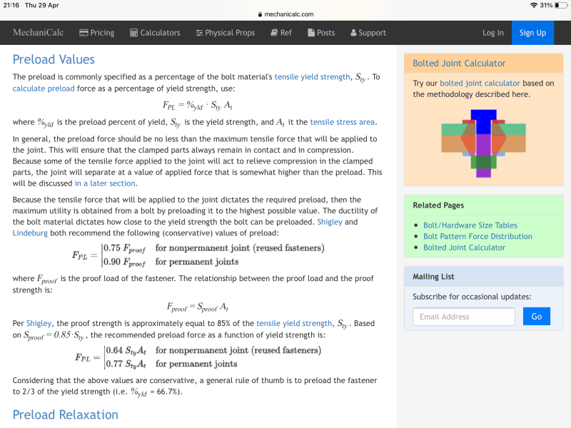
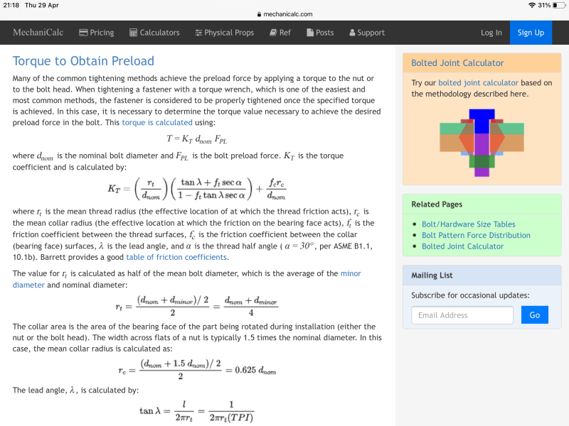
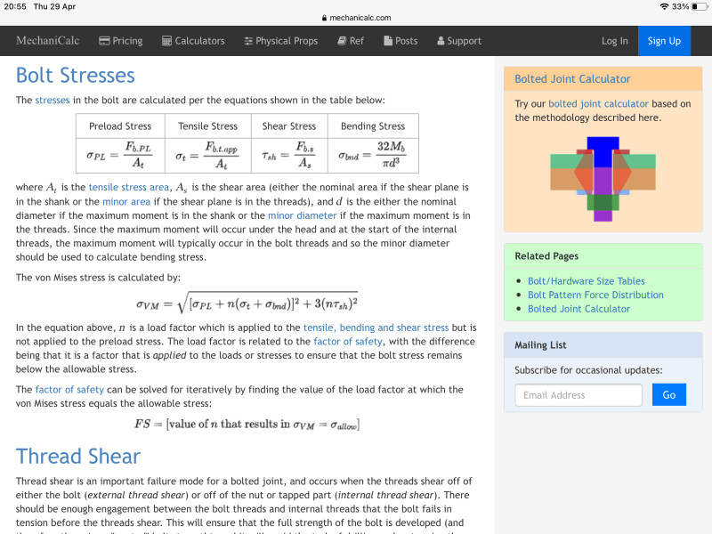
I looked at the link I posted earlier and to me the answer you seek is there, I’ve copied the relevant bits.
They basically use safety factors to negate the bending stress on the thread sections.


BFED0057-AAA4-4961-9650-5C4DAEA4D855_egog35.png


A126E773-4770-44C5-9D31-48E96572A782_k1nqzn.png
7F282BCA-F427-42DB-BB13-C1B531D08654_si9pdj.png


“Do not worry about your problems with mathematics, I assure you mine are far greater.” Albert Einstein
 
Hi All,

Thanks for the feedback

@RD1957 - The simpler way is not the more conservative way (unless Im misunderstanding what you are saying) because it does not include stresses that are actually there (ignores bending and shear).

@desertfox - The person who did a previous design report included it and the change will raise questions. The problem with including it is that it gives a preload value well below the 0.75-0.9 of proof strength and therefore the bolt will be more vulnerable to fatigue. Attached are example calcs.

@desert fox - I am not sure which bending stress that term is accounting for (it looks like it is the bolt bending not the threads bending, I get bending stress = 64.M/(pi).d^3 when applying the bending stress to the bolt and not the threads so I dont know why there is a 32 in theirs. I am also confused about the von mises equation because that is not the formula I am used to. also they say that they dont apply the load factor to the preload but in my example the bending stress is mainly due to the preload so if I do it like they did then I will be applying the load factor to the preload via the bending stress.

kind regards
Michael
 
 https://files.engineering.com/getfile.aspx?folder=3e5e4aab-f846-48ce-aa51-942373275ff2&file=calc_example.pdf
Hi Michael
I believe the 9o% proof stress is the combined stress during tightening and not the axial force left in the bolt after the torque wrench is removed. Note at the bottom of the screen shot 1 it states a rule of thumb of preloading a bolt to 2/3 of yield strength.
In the bolt stress screen shot it talks about the bending on the threads where it states :- maximum moment is in the shank or minor diameter of the screw. In the same area about the maximum moment it talks about a load factor n which is applied to the loads but not to the preload to ensure that the bolt stress stays below yield.

Thanks for the example but I cannot go through it properly because it doesn’t tell me the bolt size, preload value, or the C value or pitch of thread so I can’t do a lot with it although I think I managed to calculate the bolt size as being 5/8” is that correct?

“Do not worry about your problems with mathematics, I assure you mine are far greater.” Albert Einstein
 
Status
Not open for further replies.

Part and Inventory Search

Sponsor