Continue to Site

Eng-Tips is the largest engineering community on the Internet

Intelligent Work Forums for Engineering Professionals

  • Congratulations KootK on being selected by the Eng-Tips community for having the most helpful posts in the forums last week. Way to Go!

Fastener stresses

Status
Not open for further replies.

maatjie_mike

Mechanical
Jan 25, 2021
20
Hi,

I am doing pretty standard bolt calculations and noticed a difference between the power screw and regular fastener calcs. The fastener situation I have is bolts holding a pressurized pipe flange together (ie. external load is in the same direction as the preload (or rather opposite direction but same axis))

The textbook im using is shigley and a lot of sources on the net but I cannot find a solution to the questions below (please see attached pic for ref):

1) For power screws Von Mises is used to combine axial stress, thread bending and thread shear due to rotation. I know that the thread shear stress due to rotation is zero but why isnt Von Mises used to combine the axial and thread bending for normal fasteners?
2) Why isnt thread shear due to applied force taken into account?

All examples equate the preload force to 75% or 90% of the proof strength (or rather the force that produces the proof strength in the minimum area of the fastener). adding the external force will slightly increase the tensile stress in the bolt but not enough to exceed the proof strength. Now if you combine the tensile stress and the bending stress using Von Mises then the stress in the fastener exceeds the proof strength which means the bolt will yield (fail). when doing power screw calcs this bending stress is taken into account but not when doing normal fastener calcs.

If the reason is the shape of the thread, which approach do I use if using ACME thread for a regular fastener?

Kind regards
Michael Mullineux


 https://files.engineering.com/getfile.aspx?folder=912bfb3d-25a2-4881-9026-1df5566e670d&file=thread_stresses.PNG
Replies continue below

Recommended for you

Hi desertfox,

Thanks for replying.

When you say it is the combined stress during tightening, which stresses make up that combination and how are they combined?

2/3 of yield is roughly equal to 75% to 90% of proof strength (which is what I am doing), I think im missing your point with that sentence.

The VM equation that they use in your post doesnt make sense to me (it doesnt have all the terms in the sqroot and they add stresses that are not in the same direction in the same ()^2 brackets) can you explain?

They say that the max BM is at the root or shank but they are talking about the MB of the entire bolt not the BM due to the vertical force on the tooth (see attached pic, highlighted). This is a very helpful website but it unfortunately does not answer the questions I am asking.

Im more interested about the method not the values (the UF show that the axial stress is 0.58 of the allowable yield but the UF of VM is 0.974, but in shigley they equate the axial stress to the allowable yield for fasteners, and if I do that then the VM calc is way over yield. For power screws they equate VM to the allowable yield, [highlight #FCE94F]why?[/highlight])

If it will help you here are the values you are looking for.
-The bolt size is 12pt. cap screw: 3/4"-10UNCx2.5" LG
-the preload is 11191.047 lbf
-the C value is 0.107

Kind regards
Michael

 
 https://files.engineering.com/getfile.aspx?folder=6e9c772d-2804-4b0b-b26a-720c2d45a58c&file=bending_moment.PNG
Hi Michael
Under the heading of bolt stresses it states about using the minor of the bolt when the maximum bending moment occurs in the threads see highlight, this is the same bending stress they use in power screws.

I will answer your other points later


Bolt Stresses
The stresses in the bolt are calculated per the equations shown in the table below:

Preload Stress Tensile Stress Shear Stress Bending Stress


where At is the tensile stress area, As is the shear area (either the nominal area if the shear plane is in the shank or the minor area if the shear plane is in the threads), [highlight #EDD400]and d is the either the nominal diameter if the maximum moment is in the shank or the minor diameter if the maximum moment is in the threads. Since the maximum moment will occur under the head and at the start of the internal threads, the maximum moment will typically occur in the bolt threads and so the minor diameter should be used to calculate bending stress.[/highlight]


“Do not worry about your problems with mathematics, I assure you mine are far greater.” Albert Einstein
 
Hi Michael

go to the worked example of the helicopter shaft for a combined stress of torsion and tensile similar to what you have on the bolt or fastener, click the link below


“Do not worry about your problems with mathematics, I assure you mine are far greater.” Albert Einstein
 
Thanks, maybe your follow-up answers to my previous post will help.

@desertfox - please give me the formula and the variables you would use to work out the bending stress because I still think there is confusion with the bending stresses we are talking about, I am not talking about the bolt itself bending, Im talking about the thread of the bolt bending and the thread of the bolt shearing. The site you posted is talking about the shear being across the diameter of the bolt and the bending moment if the bolt is offset not because of the loading on the thread of the


I dont see how the helicopter example applies to my problem, could you please explain?
 
Hi Michael

The thread bending is what’s it is talking about I will try to post something later but can you please explain what this device is, all we are talking about is a bolt thread, it will help me to help you, also the calculation example you posted, that ignores shear of the threads,is this your calculation or someone else’s?
I calculated the external load in the example you sent but again is that example related to the 3/4” bolt size you mentioned. So I really need all the information you have to help you further and also the grade of bolt material.

“Do not worry about your problems with mathematics, I assure you mine are far greater.” Albert Einstein
 
desertfox, he's taking a microscopic look at bending of the screw thread, not the larger behavior of the entire fastener. In particular at the root of the thread analyzed as a stub beam.
 
If they are talking about thread bending why do they say "A bending moment could exist in the bolt if there is a gap between the plates (i.e. due to a gasket) or if there are long spacers used in the joint:"?

They are calculations that someone else did, I am using them as a method to follow.

It is a block that holds a pipe to a wall but it doesnt matter what the device is, it is literally just the bolt (technically a screw) I am concerned about.

The bolt spec I gave you is the bolt that is being used, it is all one example that I am using to understand the method, but the example does not matter, the method and rational are the only things that matter. the bolt material is ASTM A320 L7M.

When you have the time can you respond to each one of the points in my messages because there are points that are getting left behind now:
1) Im more interested about the method not the values (the UF show that the axial stress is 0.58 of the allowable yield but the UF of VM is 0.974, but in shigley they equate the axial stress to the allowable yield for fasteners, and if I do that then the VM calc is way over yield. For power screws they equate VM to the allowable yield, why?)
2) When you say it is the combined stress during tightening, which stresses make up that combination and how are they combined?
3) 2/3 of yield is roughly equal to 75% to 90% of proof strength (which is what I am doing), I think im missing your point with that sentence.
4) I dont see how the helicopter example applies to my problem, could you please explain?
5) please give me the formula and the variables you would use to work out the bending stress because I still think there is confusion with the bending stresses we are talking about.

@3DDave - The question I need answered is "in shigley they equate the axial stress to the allowable yield for fasteners, for power screws they equate VM to the allowable yield, why is there a deference if the threaded member in the fastener example has the same stresses as the power screw example?"
 
To show you from a different source the question I have:

Link at time 0:47:00 he equates the tensile stress to the proof strength

Link at time 0:57:00 he works out all the stresses on the threaded member, at time 1:11:15 he equates the VM combination of the stresses to the proof strength

Why is there a difference between the 2? why is VM not used in threaded fasteners but it is used in power screws?
 
"If they are talking about thread bending why do they say "A bending moment could exist in the bolt if there is a gap between the plates (i.e. due to a gasket) or if there are long spacers used in the joint:"?" ... the short answer, they aren't. the moment they are talking about "A bending moment could exist in the bolt if there is a gap between the plates (i.e. due to a gasket) or if there are long spacers used in the joint" is bending of the bolt shank and not bending of a thread (as a cantilever).

another day in paradise, or is paradise one day closer ?
 
Hi rb1957

Yes okay you’re right I was looking at the bending formulae for power screw threads and thought it was the same formula that they were using in the snap shots I posted above.

Hi Michael

I cant find anything concrete to post other than yes there is a difference between power screws and bolt threads, the former are usually much larger in thread form section and they constantly taking a varying load during operation as they are used for moving objects. Bolt threads on the other hand are basically static how ever that doesn’t alter the fact that a bending stress does exist due to axial loads. I have posted a link to the bolt science website which mentions thread bending but it indicates to me that bending causes a problem more likely to manifest itself in thread tripping and usually in the design of bolted joints usually (tapped holes) that’s taken care of in the design and in the case of a nut and bolt it’s taken care of provided you select the correct grades. Sorry that’s the best I could do.


“Do not worry about your problems with mathematics, I assure you mine are far greater.” Albert Einstein
 
@3DDave - I left a comment on the video in hopes he would get back to me but emailing him directly seems better, thanks.

@rb1957 - thanks for your response

@desertfox - Thanks for the info, very helpfull

I will update this thread if Dr Yang Cao replies to my email. For now I just going to do the standard bolt calcs, If questions are asked Im going to show them the clumps of hair Ive pulled out and hope it distracts them enough to forget the question.

Thanks again to everyone for the time you have given me, I really appreciate it.

Kind regards
Mike
 
You’re welcome and if in the meantime I find anything I will post in here😀👍

“Do not worry about your problems with mathematics, I assure you mine are far greater.” Albert Einstein
 
maatjie_mike:

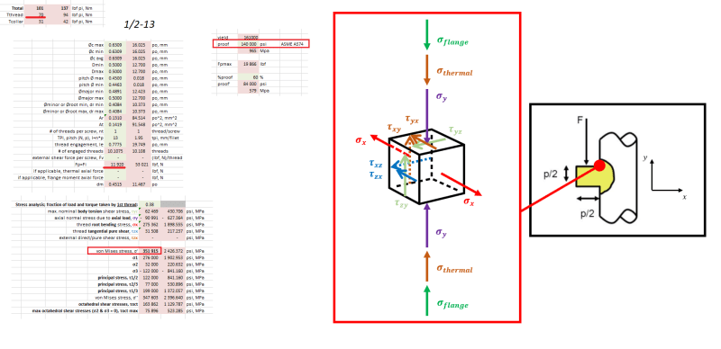
I have the same interrogation about von Mises stresses being higher than proof strength at an axial force below proof load (See picture).
thread_stress_YCT_01_11_21_xgs687.png


I am using the stress analysis provided here ( which is the same as Shigley's plus the thread (pure) tangential shear component tauZX

Did you progress on your analysis of this discrepency?
 
I continued to dig a little deeper, and I think the root bending stress discrepancy (wrt. proof strength) has something to do with the root radius reducing stress concentration factor at the root. With simple FEA simulation of a cantilever beam (developped thread), it is possible to see the impact of the root radius on the root stress.
Anyone?
 
Status
Not open for further replies.

Part and Inventory Search

Sponsor