Hello all - hoping to get some input on an issue that arose on a job.
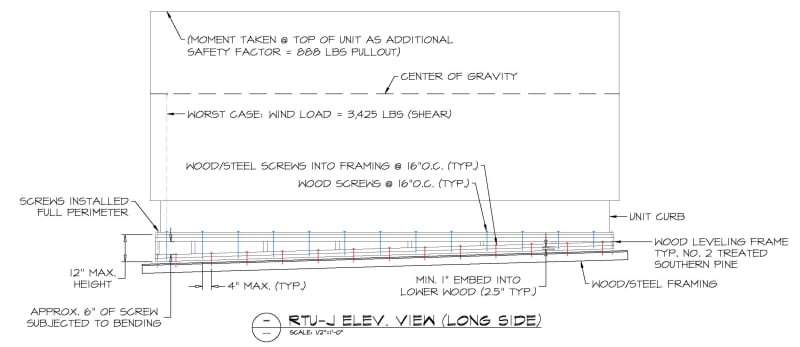
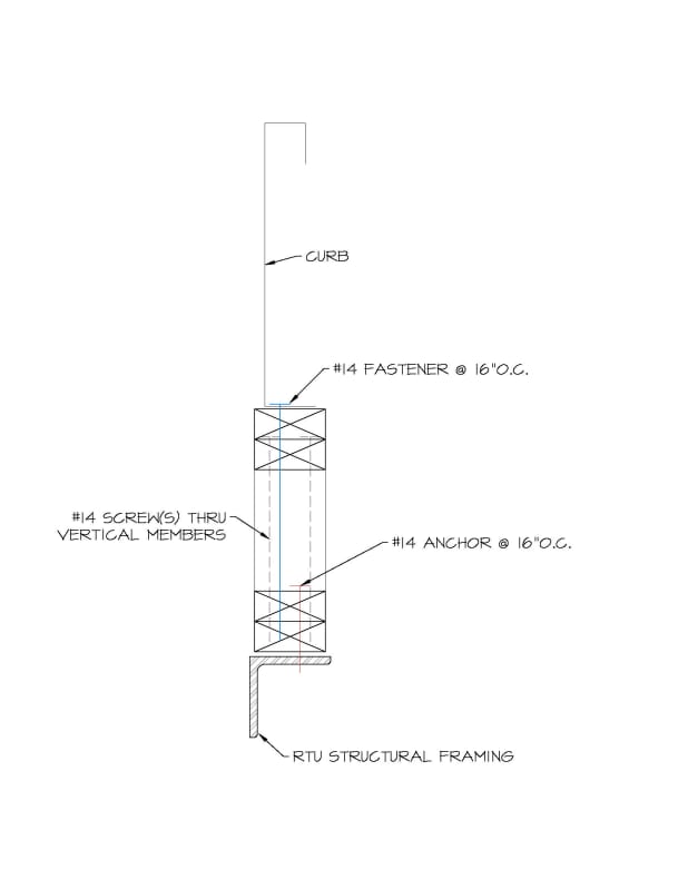
A contractor (who went a bit off script) had provided a typical leveling frame for rooftop units which were anchored to resist shear & uplift wind forces - see following sketches:
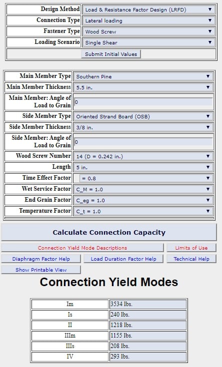
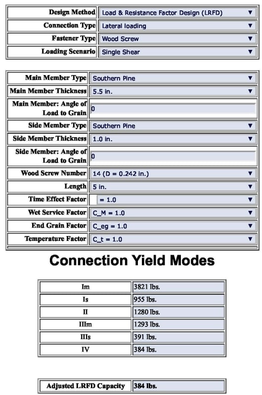
The fastening/anchoring method appears to be adequate for shear & tensile interaction forces, but bending was brought up as an issue...
A third-party reviewing entity claims that the blue fasteners fail under the bending stress induced in the screw; these screws are exposed throughout the perimeter.
The moment calculation was proposed as follows: 95 lbs shear / screw _ 6" exposed + (2) 2x4's @ top
95# (2x1.5+6) = 855"#
I get the bending yield strength of the screw to be 96"# < 855"# --> FAIL
Does this seem right? Will the wood frame itself not account for any of the bending stress?
I can accept that the leveling frame is essentially a cripple wall (as constructed) instead of continuous blocking (as originally detailed) and isn't great for resisting any lateral forces, but find it difficult to accept that the screws are the sole element resisting bending as installed.
Any help/insight/assistance would be greatly appreciated.
A contractor (who went a bit off script) had provided a typical leveling frame for rooftop units which were anchored to resist shear & uplift wind forces - see following sketches:
The fastening/anchoring method appears to be adequate for shear & tensile interaction forces, but bending was brought up as an issue...
A third-party reviewing entity claims that the blue fasteners fail under the bending stress induced in the screw; these screws are exposed throughout the perimeter.
The moment calculation was proposed as follows: 95 lbs shear / screw _ 6" exposed + (2) 2x4's @ top
95# (2x1.5+6) = 855"#
I get the bending yield strength of the screw to be 96"# < 855"# --> FAIL
Does this seem right? Will the wood frame itself not account for any of the bending stress?
I can accept that the leveling frame is essentially a cripple wall (as constructed) instead of continuous blocking (as originally detailed) and isn't great for resisting any lateral forces, but find it difficult to accept that the screws are the sole element resisting bending as installed.
Any help/insight/assistance would be greatly appreciated.