Continue to Site

Eng-Tips is the largest engineering community on the Internet

Intelligent Work Forums for Engineering Professionals

  • Congratulations waross on being selected by the Eng-Tips community for having the most helpful posts in the forums last week. Way to Go!

Fasteners subject to Bending

Status
Not open for further replies.

CPBe

Structural
Nov 4, 2019
17
Hello all - hoping to get some input on an issue that arose on a job.

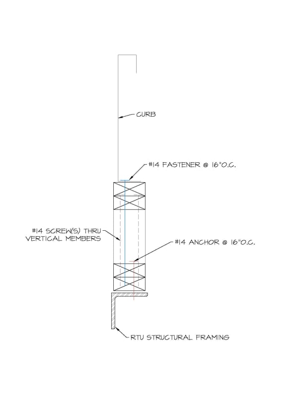
A contractor (who went a bit off script) had provided a typical leveling frame for rooftop units which were anchored to resist shear & uplift wind forces - see following sketches:
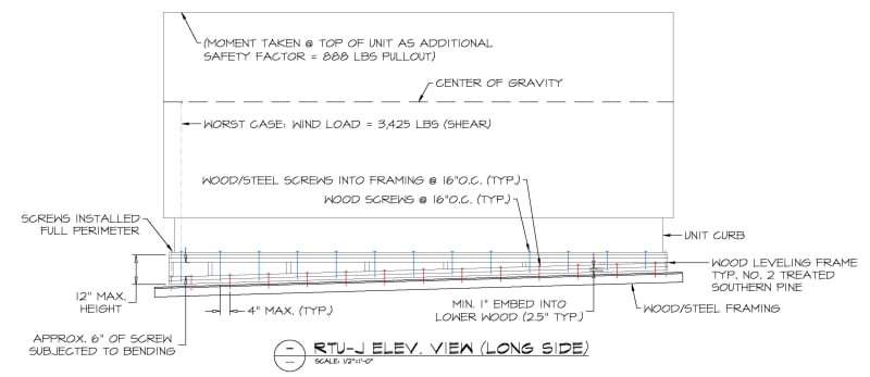
RTU-J_elev_qs6fky.jpg

RTU-J_detail_ptzcyu.jpg


The fastening/anchoring method appears to be adequate for shear & tensile interaction forces, but bending was brought up as an issue...
A third-party reviewing entity claims that the blue fasteners fail under the bending stress induced in the screw; these screws are exposed throughout the perimeter.
The moment calculation was proposed as follows: 95 lbs shear / screw _ 6" exposed + (2) 2x4's @ top
95# (2x1.5+6) = 855"#
I get the bending yield strength of the screw to be 96"# < 855"# --> FAIL

Does this seem right? Will the wood frame itself not account for any of the bending stress?
I can accept that the leveling frame is essentially a cripple wall (as constructed) instead of continuous blocking (as originally detailed) and isn't great for resisting any lateral forces, but find it difficult to accept that the screws are the sole element resisting bending as installed.
Any help/insight/assistance would be greatly appreciated.
 
Replies continue below

Recommended for you

Doesn't answer your question, but I'd simply throw some ply on the outside, nailed off at suitable centers around the perimeter. Easy fix to get everyone of your back and improve things by taking the heat off the screws.

 
I agree that's the simple solution, but not that simple after everything has already been roofed in...
(The concern had been brought up months after everything was installed.)
 
Is there a way to show with calc's that the fastener will still hold everything together but deform?
 
Looks like you're only (likely) hope would be at the "shallow" end where there is no separation between the top plate and sole plate of your "cripple wall." In those areas, the screws won't be in bending. If you can show that those can take all the shear, you may be ok.

I don't think you can take the deformation route. Each screw is a different length, and the deformations won't be equal. If the screws are the only thing resisting lateral movement, then any deformations will cause rotations at the stud to plate connections. I doubt they'd handle them very well.

In short, if you can't get justify the screws in pure shear taking all of the shear load, the contractor needs to fix his mistake. And, as you said, the contractor went off script - make sure he's paying you to justify the fix (it's worth it to him to not rip off the roof, so you should get some of his cost savings for your work).
 
Hmm...I think the only way to get that to work is by assuming a type Im connection yield mode, but this should be considered as a type Is - would you agree?
 
If your top plate is a double 2x and your sole plate is a double 2x and they meet with the fastener in (nearly) pure shear, Im and Is should be equal in a single shear connection if I'm not mistaken. Of course you'll have to check II, III, and IV, too.
 
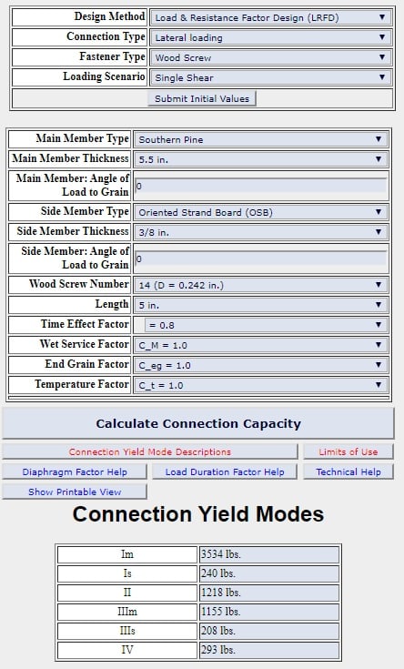
AWC's connection calculator gives the following:
AWC_connection_yield_modes_cmitfs.jpg

IIIs is obviously the weakest link @ 208 lbs, but I'm not entirely sure that's the yield mode in this scenario...
I understand that any yield mode could occur & need to design for that but I'm wondering if one of the other scenarios could be safely "assumed" and maybe coupling that with wood-to-wood friction forces to help resist shear forces could be argued...?
 
With no "gap" between the #14 fastener & the wood could yield modes Im, Is, or IV be assumed?
 
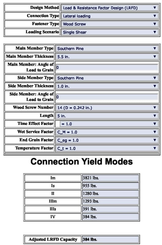
Sorry, didn't adjust that auto-filled value - see below:
AWC_connection_yield_modes_southern_pine_side_bd3cjz.jpg
 
Guess that actually answers my last question.
Thank you so much for your help! It's greatly appreciated!
 
I'm still not so sure about your calculator result. You have a 5.5" main member and a 1" side member, but your detail shows two 2x's for each (so they would both be 3" assuming adequate built-up fastening), and you have a 5" screw which would embed 4.5" into your main member here while the detail you posted says 1" minimum.

You also have LRFD selected. Did you really design that using LRFD? I know the provisions for wood LRFD obviously exist, but I always thought their use was more of an exception than a rule.

Make sure you read every line of input and every one of the exceptions. I imagine there's a potential for wetting on this - by condensation if not rain - so a Cm of .7 may be appropriate.
 
Status
Not open for further replies.

Part and Inventory Search

Sponsor