Hello All ,
My idea is not to let anybody down , but just want to learn from you guys .
So , if you think I am wrong then please correct me , but please dont make fun , because
like generator I also have my " DAMAGE CURVE ".
Please find my views in red and there are some questions asked , if you can reply , I will be greatful , but if you are not interested then also its ok .
======================================================
Back to the Original Post which has to do with the available fault current.
The fault current is dependent on both the rated current, the rated voltage or EMF and the %Impedance.
The actual impedance is a machine characteristic and does not change.
[highlight #EF2929]-------I am not saying you are wrong , but there is more to it , as explained below
------[/highlight]
The rated current is used by definition and does not change.
The rated voltage and the % Imp may change.
[highlight #EF2929]---------
I dont know what do you mean when you say rated voltage may change . If the generator is 11KV , it is supposed to produce L-L 11KV ,
please correct me if I am not understanding .
Yeah the % impedance change from STran to Tran to Syn Imp.
---------[/highlight]
The basic operating limit on an alternator is the rated KVA.
KVA is derived from rated current times rated voltage times 1.73
The first limit on current is I2R loss in the armature winding.
[highlight #EF2929]-----
Thats true I2R , and this info is provided by the generator vendor in the form of generator damage curve .
------[/highlight]
There are other limits that are subject to change.
The fault current is determined by the alternator characteristics and the operating voltage.
[highlight #EF2929]--------
Ok , but why dont you say to check the capabilty curve for all this limitations .
--------[/highlight]
This set is rated at 2500 KVA at 480 Volts. This gives a maximum current of 3007 Amps. Bolted fault current = 30,070. Amps
The rating is subject to change.
This may be a prime rated set. A prime rated set may be operated at 110% output for one hour out of 12 hours or 24 hours.
As a prime rated set, the maximum allowable current will be 3007 x 1.1 = 3308 Amps.
However the %Imp is calculated based on the set rating and the bolted fault current is still 30.008 Amps.
[highlight #EF2929]------
Ok
-----[/highlight]
If this is a diesel set it may be suitable for operation at 416 Volts. The KVA rating will drop to 416 x 3007 x √3 = 2700 KVA.
The rated maximum current will still be 3007 Amps but now there is less EMF to drive the current, the bolted fault current will drop and the %Imp will increase in the ratio of 480:416. The new %Imp will be 10% x (480/416) = 11.5%
Operated at 480 volts it takes 48 Volts to drive 3007 Amps through a bolted fault. 48V/480V = 0.1 or 10%
Operated at 416 volts it still takes 48 Volts to drive 3007 Amps through a bolted fault. 48V/416V = 0.115 or 11.5%
[highlight #EF2929]------
Can you please explain , how you reached on this conclusion """ Operated at 416 volts it still takes 48 Volts to drive 3007 Amps through a bolted fault""""
------[/highlight]
Considering the alternator rating as a factor of the prime mover power is interesting but not always valid.
I mentioned a 600 KW set that would not put out over 600 KW.
[highlight #EF2929]----
OK , but we always make sure that our PM works for 110% for 30 minutes , when we design our offshore power plants.
----[/highlight]
This was a tired old set, older than many of us here. As a prime power set it should have been capable of 660 KW easily.
It may have had a top end overhaul at 15,000 hours and was now long overdue for a 30,000 hour major overhaul. New or overhauled it would easily produce over 110% for one hour.
[highlight #EF2929]--------
I see , thanks for sharing your exp.
--------[/highlight]
I suspect that the fuel may have been light as well but have no evidence of this.
A change in the specific gravity of the fuel will change the power of the prime mover. Available input HP is actually quite variable. In Canada, a 10% or more difference between summer fuel and winter fuel is common.
[highlight #EF2929]---------
I see , again good to know for me
--------[/highlight]
Note: the time limitation has more to do with the life expectancy of the prime mover than with the alternator.
The point: Yes, many sets are capable of over 100% of rated KW when new. The rating is intended to apply to end of life, not new sets.
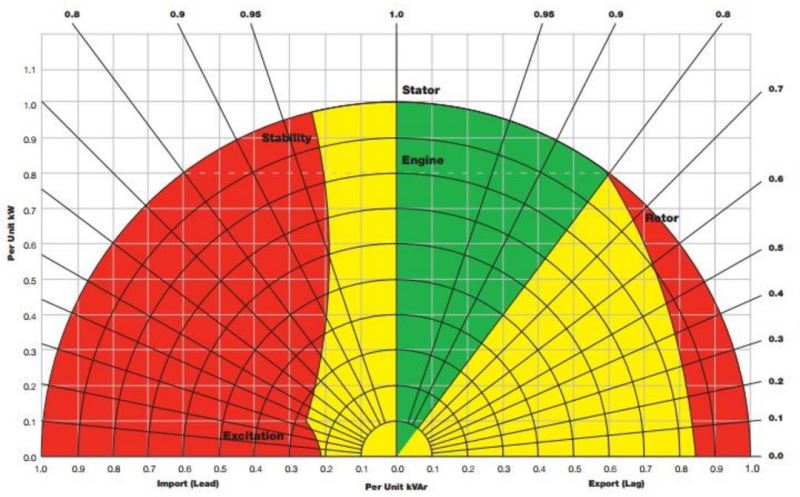
Capability curves are interesting and in some cases colourful. But what what are they based on?
[highlight #EF2929]----------
They are based on
(1)Stator Copper Loss (stator heating):
The maximum allowable heating of the stator sets a maximum
phase current
IA for the machine. It’s equivalent to set a maximum
apparent power for the machine. (Power factor is irrelevant.)
(2) Rotor Copper Loss (rotor heating):
The maximum allowable heating of the rotor sets a maximum
field current
IF for the machine. It’s equivalent to set a maximum
EA for the machine.
(3) Prime-mover’s Power Limit.
------------------------------[/highlight]
Well, a prime rated set will actually be a larger set, derated.
A 2500 KVA prime rated set will actually be a 2750 KVA set. Get the basic capability curve for the 2750 KVA set and look at the capability of a 2500 KVA set inside that curve.
Using the same set as a prime rated, 416 Volt set? Look at the capability of that 2170 KVA set inside the capability curve of a 2750 KVA set.
But what does it matter? A bolted fault is so far outside any capability curve that discussion of capabilities becomes moot.
[highlight #EF2929]---------------------
You are right , generator capability was mentioned , because since limitations of alternator were getting discussed , so capability curve became essential.
Offcourse , gen capabilty curve is not helpful in knowing the machine behaviour while a short circuit bolted fault occurs
---------------------[/highlight]
")
![[cry]](/data/assets/smilies/cry.gif "[cry] [cry]")