Continue to Site

Eng-Tips is the largest engineering community on the Internet

Intelligent Work Forums for Engineering Professionals

  • Congratulations KootK on being selected by the Eng-Tips community for having the most helpful posts in the forums last week. Way to Go!

fea on an anisotropic ring

Status
Not open for further replies.

holmesss

Structural
Feb 10, 2015
39
I have a simple ring,made of an anisotropic material (unidirectional fibers )that I would like to study in femap.
If I use the material type as "anisotropic" in femap, I will be able to insert the young modulus in X,Y and Z .
I understand that if it was a bar or a straight object,it would be easy to specify each axe.
But in the case of a ring, if I put X=100 GPa for example, this will be different at the different locations of the ring(It will become 100GPa in the Y direction for example if the ring is parallel to the XY plane).
What should I do in such cases?

thank you
 
Replies continue below

Recommended for you

Specify the elements' material orientations using a properly placed cylindrical coordinate system...
 
@jotunn thank you for your reply.
I can't use "Modify" then "update elements " "Material orientation" because the ring that I'm using is a solid.
I tried going to the "Properties" then "Material axes" , but I can find a way to make each element's direction parallel to the tangent of the ring.I cannot also use a cylindrical CSys because the ring isn't a circle.
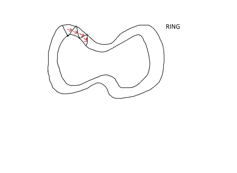
I will upload a drawing that might explain what I would like to do.(Thank you for your help because I'm really new to that).
The red arrows are the directions that I would like to have. The triangles are the elements of the Tet mesh of the solid.
What I have now is that all the arrows are parallel to the X axis.
sketch_xuuuec.jpg
 
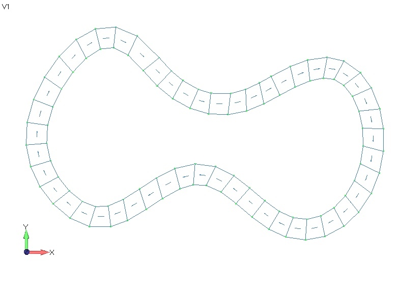
I see. IF you were using 2D elements, I'd update the elements' material orientations along a path (e.g. the periphery of your shape).

temp_c4eb5r.jpg


But, that's academic since you have 3D elements. Anisotropic 3D elements are not something I deal with often, so I'm not sure how much help I can be, but I'll take a stab at it.

In the last two-or-so years, I've only had one need to use 3D elements to model an anisotropic material. The relevant specifics were: using Femap and NeiNastran to model a layered composite using HEX (brick) elements. In doing so, I learned the following:
[ul]
[li]You have to manually edit the MAT12 card to input allowables (will not come out of femap)[/li]
[li]Allowables must be in stress format, even with a strain solution[/li]
[li]You have to add the PCOMP ID to the PSOLID card manually (will not come out of femap)[/li]
[li]Changing element orientation (solid element...first edge) doesn't seem to be possible in femap[/li]
[/ul]

As a caveat: I don't know if these were limitations of the Nei input deck output from Femap, or whether they were former software limitations which have been addressed in recent releases, or whether the "limitations" were caused solely by my ignorance of the software and were not truly software limitations.

Assuming they're still limitations, I'll offer the following, very "ungraceful" solution to your issue.

Since you cannot use a coordinate system to define your material axis, it seems you'll have to use the element axis to align your material axis. If my last bullet point lesson learned is true, you're unfortunately not able to instruct femap to change the element orientation (in other words, which edge is first edge) and you'll have to do it manually. Manually being defined as re-creating the elements, one by one, by selecting the nodes in the proper order such that your elements' coordinate system can be used as the material coordinate system. I realize it's ungraceful and extremely time consuming...but that's the best suggestion I have. I'm definitely interested to know if anyone else has a more graceful solution!
 
@jotunn , yes if it was a 2D model it would have been more simple.

The problem is that I am stuck with this 3D model, and I sort of have to find a way to do it with that..
Your last proposition seems to be interesting (Long but could be the solution).
I hope that someone maybe has a more graceful solution as you described .

Another maybe silly question : Let's say that ring has young modulus of 39 GPa in X , 12 GPa in Y and in Z.
Do you think there's a justification or a way to run this analysis by considering it as an isotropic material (IF I choose another young modulus) ? this would be much simpler , but I cannot find a reference that could let me do that.
 
orientation_oohrsc.png


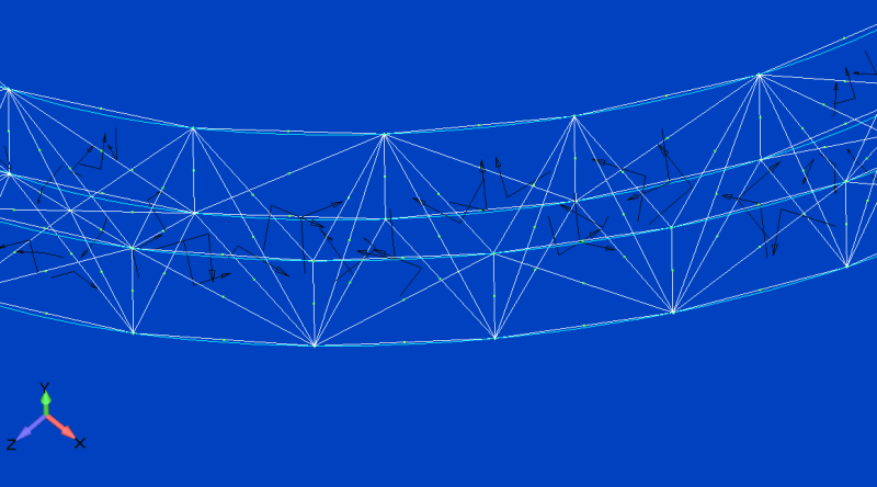
Here is what I get when I do "align by element"...
I would like to have the directions parallel to the tangent of the outer path of the curved shape.(Which seems to be hard to do with a solid).

Thanks !
 
Status
Not open for further replies.

Part and Inventory Search

Sponsor