Tek-Tips is the largest IT community on the Internet today!

Members share and learn making Tek-Tips Forums the best source of peer-reviewed technical information on the Internet!

  • Congratulations cowski on being selected by the Eng-Tips community for having the most helpful posts in the forums last week. Way to Go!

FEA results verification

Status
Not open for further replies.

uzi210

Mechanical
Joined
Jul 3, 2019
Messages
2
Location
NO
Hey Everyone,

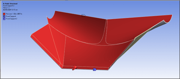
This is my first post over here. I need help with verification of FEA results. The simulation consists of a plate exposed to a uniform load on it. The tricky part is that the plate has a complex shape as shown in the photo.

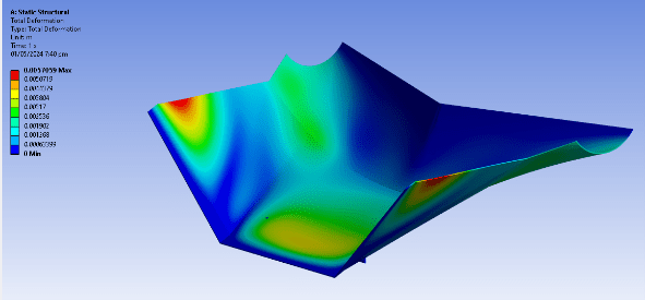
How does one verify results for complex shapes? I tried hand calculations, assuming simple beam and plate, but the results showed a error of more than 45%.

Any advice would be appreciated.

FEA_nhjlj0.png
 
You should verify your modelling approach (code, element type, mesh size, properties, boundary conditions, etc) using a simple model, such as a flat plate, that you can analyze using a close form solution.

Also, always plot the deformed geometry before looking at any other results. If the deformation does not look plausible the model is likely wrong.
 
it looks like the bent sides are really supporting the flat faces, so the faces bulge independently (and away for the sides. As above, look at the deformed shape.

if this is the behaviour, then hand calc the flat faces, under pressure.

like greg says, these will rapidly adopt a membrane behaviour, with large displacements (important for your FEM). "normal" shells work like plates, bending with the pressure load. But quickly the displacements become large (with respect to the shell thickness) and the shells react pressure as in-plane membrane tension.

But is a pressure load realistic ? is the plate sealed ? or are you using a uniform load (= pressure) as a simple test case ?

"Hoffen wir mal, dass alles gut geht !"
General Paulus, Nov 1942, outside Stalingrad after the launch of Operation Uranus.
 
SWComposites said:
You should verify your modelling approach (code, element type, mesh size, properties, boundary conditions, etc) using a simple model, such as a flat plate, that you can analyze using a close form solution.
I def thought about that, is this a generally acceptable way to validate results?

GregLocock said:
The boundary conditions are rather important but perhaps you could approximate it as a hemisphere.
I guess I might get better results if I approximate it as a hemisphere but that will make it even more harder to do hand calculations. Any suggestions on what equations can be used?

rb1957 said:
if this is the behaviour, then hand calc the flat faces, under pressure....But is a pressure load realistic ? is the plate sealed ? or are you using a uniform load (= pressure) as a simple test case ?
Maybe the flat sides can be checked with hand calc.

PS. I have used uniform load. Boundary conditions and load are shown in the figure.

FEA-2_svjcso.png
 
yeah, that image is about as "clear as mud".

pinned constraint along all the edges ?

uniform normal load on all the faces ?
what loads are going to be applied ? (uniform sounds like a test load)

"Hoffen wir mal, dass alles gut geht !"
General Paulus, Nov 1942, outside Stalingrad after the launch of Operation Uranus.
 
There are two levels of "verification" typically needed:
- the basic modelling approach as I outlined above. Yes, this is accepted as a practical way to verify the generic modelling approach. If this doesn't check out then don't even bother with the next level.
- part specific modelling approach - this is quite a bit more complicated. Start with checking displacements. Then check constraint forces. Check mode shapes if doing a dynamic analysis. Are all of those realistic and plausible? Then look at stress or strain distributions, again are they plausible? or are things over or under constrained? In the end, the only real "verification" comes versus actual part test data, which may or may not be required depending on your application.

It would help if you show a deformed geometry plot (NOT a contour plot of displacements)

Also, show a picture of the actual part, and describe how it is loaded and constrained in reality.

 
Could you show an assembly drawing, clearly showing the interfaces between parts. Can you also show where and how load is applied. Seeing the ‘whole picture’ will permit the manner in which the part reacts (predict load paths, derive FBD, determine deformation, etc) to be assessed.
 
Status
Not open for further replies.

Part and Inventory Search

Sponsor

Back
Top