Continue to Site

Eng-Tips is the largest engineering community on the Internet

Intelligent Work Forums for Engineering Professionals

  • Congratulations KootK on being selected by the Eng-Tips community for having the most helpful posts in the forums last week. Way to Go!

FEA Theory: Element stress vs nodal force 1

Status
Not open for further replies.

canadiancastor

Structural
Apr 13, 2014
34
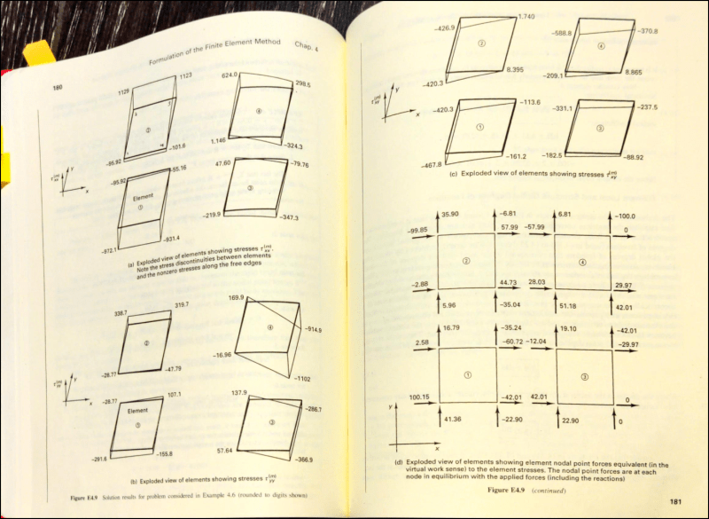
I'm trying to understand an example in Bathe's Finite Element procedures, but there is something I'm missing. He goes from elements stress to equivalent nodal point forces (he says "in the virtual work sense"), but I don't understand he's doing the transition. Can the forces at element nodal points be fully determined by the element stress only, and can I do it simply by hand?
PP_2024-02-15_08-20-57_xvjtgl.png
 
Replies continue below

Recommended for you

it is not so simple. The FEA knows how much of the element is effective at each node, how to convert local stress to load.

"Hoffen wir mal, dass alles gut geht !"
General Paulus, Nov 1942, outside Stalingrad after the launch of Operation Uranus.
 
I'll look at the book later, but FEA first solves for nodal forces and displacements, then calculates element stresses from those results.
 
On that sheet, he is using 2D/flat/plate elements that are rectangular, laid out on a square grid, with linear stress/strain across the element, so yes, you should be able to work things out by hand. Most FEA problems don't include these simplifications, so in a general case, not so easy.
 
I believe the stresses come from application of (4.12) and (4.11) once the element displacements have been determined, the element in the example utilized linear shape functions for H and the figures there show that stress discontinuities exist between element boundaries and that the stresses vary linearly on any edge. I believe the forces come from application of the general KU=R equation (4.17) in which K is determined via virtual work leading to equation (4.19). I read this to show that the figure illustrates that the same B and C matrix which produce stress discontinuities at the element boundaries produces/maintains force equilibrium at each of the nodes.
 
The solution gives nodal displacements and rotations. From these, the nodal forces and moments are calculated elementwise (Ku=f), and if the material properties vary at adjacent elements (no unique "nodal force" or "nodal moment" available), the solution at a node will typically be presented as an average or weighted average of the forces and moments at integration points (which can be e.g., 1 or 4 in number in a quadrilateral shell).

The values "inside elements" are interpolations constructed as a sum of shape functions multiplied by nodal values. These can be found by hand, but typically only mid-element, Gauss-point or nodal (or average nodal of all adjacent elements) values are used in practice.

Equilibrium in FEA is not necessarily satisfied pointwise (in nodes or elsewhere), as previously described (imagine four quads in forming a square, with each quad having different Young's modulus). Instead, an integral equality is preserved - integral of the interpolant multiplied by the residual of the differential equation equals the integral of the external load multiplied by the interpolant. The energy (work) contained in "the element" (for a 1D element, think of the area under a curve and for a 2D element, think of the volume under a two-dimensional curve z=f(x,y)) equals the energy (work) excerted by the applied load.
 
Thanks for the insights guys. I guess I'm still wondering how I would go about going from nodal values to plate internal stresses or the other way around? Is it a matrix calculation that I have to do all at once? Does it depend on my plate porperties and dimensions?
 
Start with a beam or bar model and extrapolate the concepts from there. Many books which cover the complete process for beams and bars. And of course the solution is a function of the plate properties and dimensions.

If you just want to understand the concepts for plates, then understanding the fundamentals of the FEM is enough. One calculates primary variables (e.g., displacement and rotation) in nodes (solution of a linear equation system by numerical matrix algebra), then one can compute secondary variables (e.g., forces or moments and from those, stresses) in nodes from definitions (Ku=f), and also between nodes (midpoint, Gauss points or elsewhere) with the interpolant and definitions - for the beam: M = EI*dw/dx^2. For the bilinear plate interpolation, moment and shear are constant in areas between nodes (in "elements"). For a biquadratic plate interpolation, moment and shear are linear between nodes.
 
I happen to work with several outstanding programmers who worked with Dr. Bathe for years on ADINA. They are not on EngTips, so I'll paraphrase some of their comments.

The key is the note saying "virtual work sense"... it's the the entire essense of FEA, to use the principle of virtual work to get from stresses to forces. That is the point of the example. Read that section very carefully, especially equation (4.29) in that section.
In linear analysis, starting from displacements, the nodal forces can be calculated in two equivalent ways:

a) R_e = K_e * U_e
b) At each integration point, calculate strains using B(m) * U_e, calculate stresses using C*e, then integrate stresses using Eq. 4.29.

R_e: element nodal force
K_e: element stiffness matrix
U_e: element displacement vector

Neither method is easy to do by hand, since K_e is not easy to do by hand.
ADINA code often uses Eq. 4.29, but that requires the information of integration points.
 
you're asking sensible questions, that can be answered by almost any FE text. I'm guessing you're in school, which year ?, or self-study.

I learnt, very many years ago, by studying very simple structures, like trusses, where you can go through the whole FE method by hand.

The next level learning is doing single element tests so you really understand how the elements work, where they work well, ok, and badly.

"Hoffen wir mal, dass alles gut geht !"
General Paulus, Nov 1942, outside Stalingrad after the launch of Operation Uranus.
 
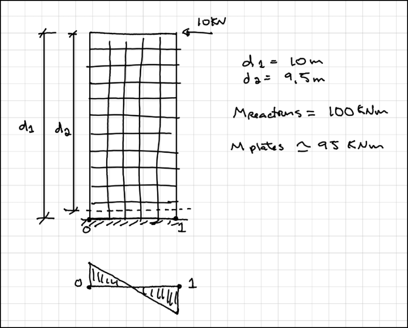
@rb1957 I've been practicing for about 10 years. I ran into this issue trying to integrate axial membrane loads at the bottom of a shear wall made of plates. When integrating at the "bottom" of the wall, that is, right next to the supports, and multiplying by the lever arm, I'm getting 2-5% less moment than Id expect. If I do the same for the reactions, I get the right moment. That's what is driving me back to basics.
The individual and global beam stiffness matrices are simple enough, they can be determined one by one and assembled. The plates don't seem to be quite as simple, as you can see in this thread.
 
ok, that explains things. Plates aren't so simple, but the stiffness matrix is well defined in texts,

So how did you determine the loads ?

"Hoffen wir mal, dass alles gut geht !"
General Paulus, Nov 1942, outside Stalingrad after the launch of Operation Uranus.
 
canadiancastor:
one source of your force discrepancy likely stems from the fact that the integrals are evaluated numerically at gauss points within the element and then interpolated/extrapolated out to the nodes/interior polling stations, so the most accurate (but still approximate) stress values occur at the gauss points within the element.
 
@Celt83 I'm not sure I understand how the Gauss points relate to all of this yet (where are gauss points in the original pages that I posted? Is it complexity that is brushed over?), but this makes sense with the results that I'm seeing. If I consider the lever arm for the moment to be from the top of the shear wall to the half way point of my first plate, it seems to work out. I added a sketch to illustrate what I mean. I can sort of validate this hypothesis by making the first plate very small in the Y direction: it works, the moment at the base goes up.
PP_2024-02-16_11-21-53_zxrij7.png
 
You should read the manual of the computer program you use. There, or in the graphical user interface, the source of internal forces (Gauss point values, nodal values, nodal average from adjacent Gauss points, mid-element or elsewhere) should be given, and based on that, you can determine the cause of discrepancy.

Have you tried refining the mesh and tracking the change in results? Also, note that shell elements have in-plane shear force (Nxy) and transverse normal force (Nx) which contribute to axial stiffness and force (the effect should be noticeable near the clamped boundary condition), which I assume you did not account for in your hand-calculation. That, as well as averaging/smoothing/mid-element values can easily explain the 2-5% difference.
 
Status
Not open for further replies.

Part and Inventory Search

Sponsor