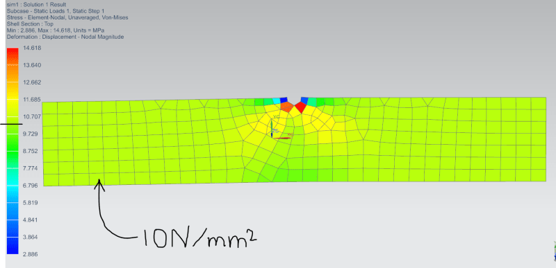
Im trying to mesh and simulate stress in a simple 2d example.
This represents a 1x20x100mm flat piece of steel under stress.
There is a stress concentration (notch) in the middle, with diameter 2mm.
I have been reducing the element size gradually to find a convergence value for maximal stress at the notch. But when I get down to element size 0.003mm, this happens:
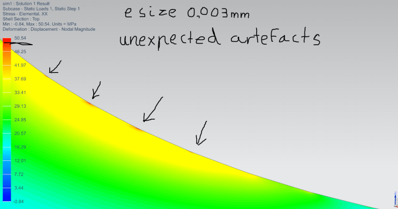
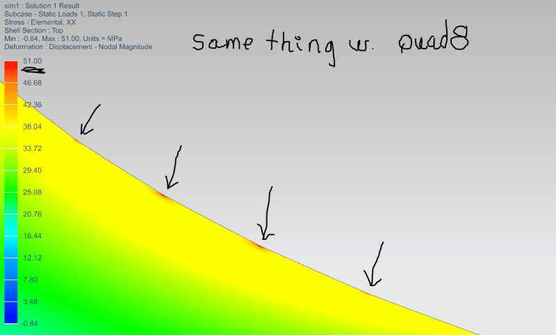
Now, clearly the curve of the notch (radius 1mm) has not been interpreted as a curve, but as a many-sided polygon. The elements are smaller than the sides of this polygon, so the error is in the curve itself, or in the mesh interpretation of the curve.
So, how do I get the curve to act as an actual curve, or at least up the rezolution?
This represents a 1x20x100mm flat piece of steel under stress.
There is a stress concentration (notch) in the middle, with diameter 2mm.
I have been reducing the element size gradually to find a convergence value for maximal stress at the notch. But when I get down to element size 0.003mm, this happens:
Now, clearly the curve of the notch (radius 1mm) has not been interpreted as a curve, but as a many-sided polygon. The elements are smaller than the sides of this polygon, so the error is in the curve itself, or in the mesh interpretation of the curve.
So, how do I get the curve to act as an actual curve, or at least up the rezolution?