Hello, I am trying to simulate the effect of manufacturing deviations from CNC on flexures, such as the wavy effect left on the surface. To do this, I set an ideal/clean model and compare the stresses to one with specific deviations. I need to be consistent with the frequency and amplitude of the waves I consider on the defected models, so that creating an offset and manually setting a spline curve choosing points from the original curve and the one of the offset does not work.
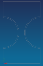
Besides, the curves are sometimes perfect semicircles, ellipses with varying major and minor radius, as well as linear regions followed by a semicircle. Any idea how can I draw this properly on an sketch, to further extrude it and analyze it? In the attached picture you can see an example of a circular flexure, with the curved region where the wave needs to be applied. Thank you so much in advance!
Besides, the curves are sometimes perfect semicircles, ellipses with varying major and minor radius, as well as linear regions followed by a semicircle. Any idea how can I draw this properly on an sketch, to further extrude it and analyze it? In the attached picture you can see an example of a circular flexure, with the curved region where the wave needs to be applied. Thank you so much in advance!