Continue to Site

Eng-Tips is the largest engineering community on the Internet

Intelligent Work Forums for Engineering Professionals

  • Congratulations KootK on being selected by the Eng-Tips community for having the most helpful posts in the forums last week. Way to Go!

FEM Slab design peak moment 1

Status
Not open for further replies.

Ocean168

Structural
Aug 28, 2021
8
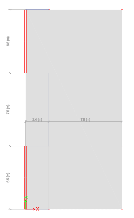
I am using FEM to verify my hand calc of the slab as shown below. a 800 deep beam has been adapted to span from one wall to another.

1200_yztmew.png


With hand calc for slab, I will simply treat the beam & walls as the same - supports.
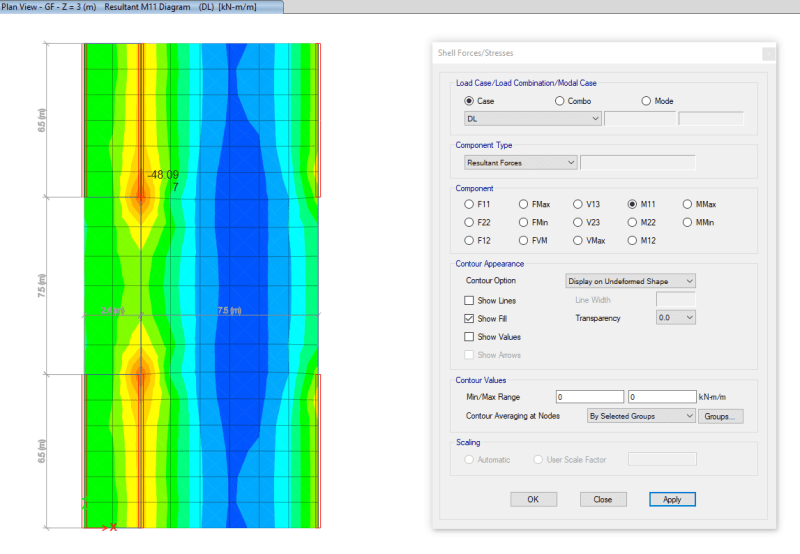
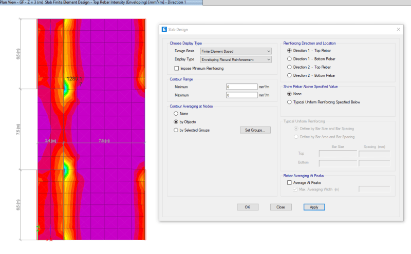
With FEM, I am getting a lot higher moment at wall ends and extensive reinforcement at wall end area, which is fair.

22_ycqgrb.png

33_g2nmac.png


I understand that you can define a strip of a certain width to average the peak moment but still it will be a lot higher that other locations along the walls.
What happens if I design using hand calc without designing anything special for this zone?
What can I do in my model to make the slab more 'reasonable'?
 
Replies continue below

Recommended for you

This is relevant to me at the moment as I am doing a similar task.

I believe that modelling the true nonlinear moment-curvature response of the slab would tend to more evenly smear out that peak bending moment, as cracking and moment redistribution would help in these high moment regions near the wall ends. However it’s not always practical and requires a nonlinear analysis.

Averaging the bending moment based on the linear analysis over a wider region is effectively doing the same thing, but you’re sort of relying on intuition to judge what is a reasonable amount of averaging.

I’m a big believer that reinforced concrete is a pretty forgiving material, and you could design almost any RC structure with some very simplistic assumptions and rely on moment redistribution and ductility to sort out the details, so to speak. I say that somewhat flippantly, obviously you need to be aware of the limitations of the materials and know when a certain level of higher level analysis is warranted.
 
The results obtained from the FEM are reasonable and should be expected, even with hand calculations.

Ocean168 said:
1) What happens if I design using hand calc without designing anything special for this zone?
2) What can I do in my model to make the slab more 'reasonable'?

1) What happens is you will have an inaccurate assessment of the situation. There is something special about the central region, and it should be recognized.
2) There is nothing unreasonable about the model as it is. Provide reinforcement where it is needed.

BA
 
For that type of support, I usually treated the beam as fixed ended at the wall.

Rather than think climate change and the corona virus as science, think of it as the wrath of God. Feel any better?

-Dik
 
Hi
I don see anything unexpected with the moment at the end of the wall. There might be some singularity effects directly at the end of the wall but that is to be expected. You have checked the M11 box and I expect that is some type of major moment. I would determine the design moments and shear effects including possible punching and reinforce accordingly.

Hand calculation, depending on what you mean by "hand calculation", should give similar results. I think you need to figure out how the software calculates the reinforcement, more in detail, if you haven't done that already.

Good luck

Thomas
 
I am not saying the results from FEM is wrong.
My point here is do you use 3D FEM for regular slab design like this? Because I believe the majority doesn't. And I don't think we increase reinforcement in this areas as well based on the conventional calculation we use.
So is it necessary to increase the reinforcement in these area or can we simply use the same reinforcement and allow slab the crack here and redistribute the moment?
 
If wider cracks are a problem, concentrate the reinforcement there. Otherwise, it's safe from a strength perspective.
 
Ocean168 said:
So is it necessary to increase the reinforcement in these area or can we simply use the same reinforcement and allow slab the crack here and redistribute the moment?
Yes, if I were you, I will provide the reinforcement as shown by the program. Secondly you can have a rough manual check by considering moment at the face of the support to confirm program reinforcement calculations. Finally, redistribution has its limits and that should be kept in mind.
 
Have you adjusted the panel stiffness to be closer to isotropic?

The responses so far are a bit odd, I would have figured everyone was designing continuous one-way slabs on a unit width strip basis, which as op points out would not give you these stress concentrations.

If your panel has equal or near equal stiffness in both directions and the beam is “flexible” then the stress concentrations make sense to me. You could try making the beam stiffer or adjusting the panel stiffness modifiers to force isotropy (assuming this is a one-way slab)


My Personal Open Source Structural Applications:

Open Source Structural GitHub Group:
 
I think I may have misinterpreted the drawing. Numbering walls from left to right, I assumed beams were located at lines 1 and 3 but not line 2. In that case, the slab in the central area is two-way while the north and south areas are one-way.

I am now thinking that there are beams on all three lines. If that is the case, the entire slab is one-way, but the negative moment at line 3 is reduced and the positive moment is increased due to the absence of wall at line 3.


BA
 
The issue is that your slab is not comprised of only "one-way slabs". Assuming that the areas marked with red color in your first picture represent walls, you will notice an anti-symmetry: the slab carries load in two directions in the "7.5(m) * 2.4(m)"-area and in the near vicinity of that area. There is no way to make the model "reasonable" - the results are what they are.

You will not be able to isolate "beam strips" and design according to such internal forces, but this is not an issue, since you have the FEM-results available. You have used a plate model to calculate bending (M11, M22) and twisting (M12) in each part of the slab. Therefore, I propose that you use Wood-Armer (or a similar approach that accounts for twisting moment) equations to design the reinforcement in the two orthogonal directions ("1" and "2").

PS. All slabs are two-way slabs, and the simplification of "imagining a series of unit width beams located next to each other" can be grossly unconservative if the geometry does not remind strongly of "beam" (e.g., Euler-Bernoulli).
 
centondollar said:
The issue is that your slab is not comprised of only "one-way slabs".

The attached file indicates possible beam locations in blue dashed lines. It seems reasonable to me, assuming this is the intended arrangement, that all slabs are one-way slabs. If the negative moment at the wall on line 3 is used to reduce positive moment in the 7.5m span, it would seem reasonable to add bottom bars between beams in the open area. Other than that, the design of all regions would be quite similar.


BA
 
 https://files.engineering.com/getfile.aspx?folder=f530f4af-4691-4bbc-ab47-7f53502b4fd5&file=One-waySlab.pdf
Ocean,

Please clarify where the beam(s) are located.
 
To me, the issue is that the FEM analysis shows you what the moment is at an infinitesimally small width al the wall locations. There are a number of ways I have dealt with this in the past. I kind of invented my own terminology when I was writing this up (back when I was working on the development and documentation for RISAFoundation). The methods I came up with were the following:

ACI Definition of Strips (ACI 318-14 Section 8.4.1/ACI 318-11 Section 13.2)
This section of the ACI code is really intended for elevated slabs. The requirement for "column strips" is that the width on each side should be set to 25% of the span length or width whichever is smaller. Then the "middle strip" is defined to span between the edges of the column strips.

This method requires engineering judgment for column grids that are not perfectly aligned and rectangular. In addition, when the column strip becomes very small then the middle strip may become very wide so that the entire slab is included in either a column strip or a middle strip.

The ACI strip method listed above is based on essentially 1/2 of the mid-span tributary lines. The hand calculation methods would have you design for the full tributary moments over this smaller width which should be conservative. Computer methods will design for the average moment over the assumed design width which should result in a more efficient design.

Zero Shear Transfer Method
The Zero Shear Transfer method used the shear force contours perpendicular to the span of the slab to set the design width. This should provide a result very similar to using the mid-span tributary lines, but is a bit more theoretically derived for non-rectangular column layouts. This method is described in greater detail in the PTI publication Design Fundamentals of Post-Tensioned Concrete Floors. Ideally, this method should give design strips of similar width to the ACI strip method. However, it is more rationally derived and should work better for cases where uneven column spacing makes the strip method difficult to apply.

Zero Moment Method
In a similar fashion to the zero shear transfer method, the Zero Moment method uses the moment contours to identify where the moment changes sign. This can be used to set the design strip width approximately equal to the distance between zero moments.

Shear Perimeter Method
Another basis would be to set the design width equal to the pedestal width plus a distance 'd' or 'd/2' on each side (in your case wall width + d or d/2). This will end up being a more conservative assumption for flexure than the other methods listed. As such, it would be more appropriate for situations where shear or punching shear failures are a primary concern. Examples would also include cases where the pedestal is very large such as for a vertical vessel or grain silo.

Hybrid Method / Engineering Judgment
A variation on these methods would be to start off setting the column strip using the ACI strip method. Then, if necessary, the width could be modified based on considering the other methods. This is especially true for situations where the column grid is not aligned or rectangular.

In addition, when the middle strip widths get too large, they could be set to values closer to the column strip width. The middle strip would normally be centered on the area with the highest mid-span moments. This would neglect lower moment regions between the column and middle strips. Hence the strips would designed for a higher moment per unit width. This reinforcement could then be extended into the lower moment regions between strips.
 
Many thanks.
Yes you are right. I made a mistake by comparing a two-way slab in my model with hand calculation for one way. There is no latitude beams. So I should change M22 stiffness to near 0 to simulate a one-way slab behavior if I want to compare to hand calculation for one way slab.
 
Status
Not open for further replies.

Part and Inventory Search

Sponsor