Eng-Tips is the largest engineering community on the Internet

Intelligent Work Forums for Engineering Professionals

Femap slice solid 2

Status
Not open for further replies.

LeonardoBer

Aerospace
Oct 22, 2020
19
0
0
US
Dear Femap users,

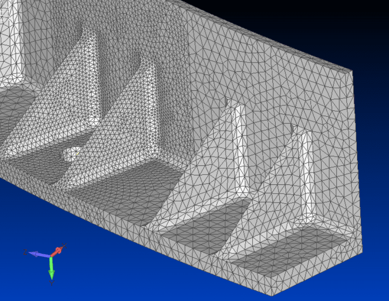
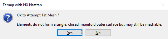
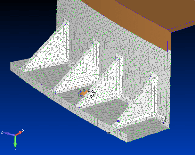
Recently I tried to slice a solid and make a tet-mesh out of the geometry, but for some reason femap did not create a face at the plane of the slice. This makes the solid not enclosed and I am unable to create a tet mesh. Anyone know what went wrong, and how to fix this?

slide_squpzm.png


msg1_auuuj5.png


notets_jfh4bf.png
 
Replies continue below

Recommended for you

Was there any errors listed to the messages window when the solid was sliced? Femap should normally enclose a solid that is sliced.
 
No, there were no errors. I repeated this process a few times and still the same result. However I did figure out how to fix it!

I created a boundary surface from the edge curves, converted that to an actual surface, and then performed non-manifold add and it became a proper solid to tet mesh.

3D_tetmesh_rpn1so.png
 
I didn't understand you wanted the hole, I thought the hole appeared and you wanted it gone ...

1) "converted that (boundary surface) to an actual surface" ... how'd you do that ?

2) don't they have a hole tool for solids ? (like they have for surfaces)

another day in paradise, or is paradise one day closer ?
 
I am assuming he used Geometry > Boundary Surface > From Curves and then selected all the curves that made the loop of the open area that was created after the slice. From there you could use Geometry > Surface >Convert, which will convert the boundary surface to normal parasolid surface. Finally you could do Geometry > Solid > Stitch. If the surfaces you select make a "water tight" connection, it will be converted to a solid. Then you will be ready to mesh.

But I am curious of why the original solid slice created an open face.
 
TG you are absolutely correct on everything youve said, and I think I my first post was misleading to rb1957. My issue was not related to the hole, sorry for the confusion. It was indeed the open cross section (not water tight per TG).

I also dont know why I got an open face like this, Ive always sliced solids in this way and never had such a problem before.
 
Dear Leonardo,
Is a problem of the geometry, all has an explanation, but without the model in hand is impossible to investigate exactly. Please post your original FEMAP model here and we can investigate the reason, thanks!.
Please note if your original solid geometry is not perfectly closed (the geometry is not a genuine solid) then is useless to try to mesh with tetrahedral elements, the TET mesher will fail for sure.

Check FEMAP in your MODEL INFO tree the icons you have for the geometry: the genuine solid is a cylinder. If the icon of your part is different, then you have a problem, the component is simply skin, a collection of surfaces. You can create a genuine solid body creating the missed surfaces and stitching all surfaces in a solid BODY using command GEOMETRY > SOLID > STITCH:
GENERAL-BODY-ADD_vavnn2.png

Best regards,
Blas.

~~~~~~~~~~~~~~~~~~~~~~
Blas Molero Hidalgo
Ingeniero Industrial
Director

IBERISA
48004 BILBAO (SPAIN)
WEB: Blog de FEMAP & NX Nastran:
 
Blas, you were right! Unfortunately I did not save a version of the model which still contains the geometry so I was not able to check what you said. However I did try and import the geometry into a new blank file and saw exactly as you had described. The icon in the tree was NOT a solid cylinder. Thanks for your great explanation.

Untitled_egt49z.jpg
 
damn! don't you just hate that ! Done it more than once ...
found something not behaving as I think it should, play around with some of the buttons, and voila! now it's behaving.
so what in the "sam heck" did I do to fix whatever it was I did in the first place ?

another day in paradise, or is paradise one day closer ?
 
Status
Not open for further replies.
Back
Top