Continue to Site

Eng-Tips is the largest engineering community on the Internet

Intelligent Work Forums for Engineering Professionals

  • Congratulations waross on being selected by the Eng-Tips community for having the most helpful posts in the forums last week. Way to Go!

Fire rating of threaded rod tiebacks?

Status
Not open for further replies.

Backcheckrage

Structural
Sep 23, 2012
84
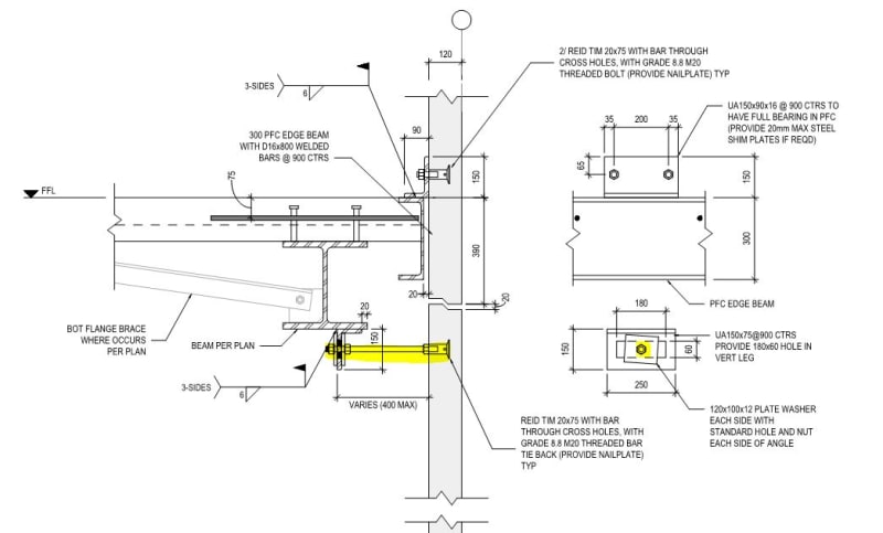
I'm working in AUS/NZ. I've got these tension-compression rods which are supporting precast cladding panels under faceload. The issue is that I need these things to be good for 60minute fire rating. How can that be checked? I tried to use formulas in NZS3404 section 11.6 (snap below) -but I only get 15mins or so. Can these things be intumescent painted? Has anyone done this before?
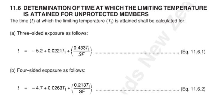
Capture_rtaml9.jpg


the detail:

Capture2_ohkko9.jpg
 
Replies continue below

Recommended for you

I'm also in NZ here

Funnily enough there was an intumescent paint code of practice presentation thing on Wednesday that I half listened to that gave some input on this
They said technically you can fire-rate ~16-20mm rods (they were talking Reidbrace & Donobrace not bolts though) but in practice you will have issues
Potential poor adhesion, damage during install, coatings don't tolerate movement well (sag in braces or bolts can damage it) etc
So - based off that I wouldn't recommend trying to fire-rate those rods that way

I've used a similar approach with fire-rating some connections to show that, even at 30/60mins (or whatever) I have sufficient capacity in my angle (or whatever it is) to sustain the fire loads
You could redesign the connection using some EA/UA sections or folded plate and make the plate thick enough to sustain it that way
I'm assuming this is only for 0.5kPa fire face load so should be a pretty minimal demand on them?
 
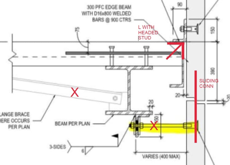
Can you do something like the below using a sliding dowel in the panel and a headed stud to the L or maybe a chunk of welded rebar?

Clipboard01_h7pxda.jpg


-----*****-----
So strange to see the singularity approaching while the entire planet is rapidly turning into a hellscape. -John Coates

-Dik
 
How is that steel beam reaching a 60min fire capacity?

Backcheckrage said:
I tried to use formulas in NZS3404 section 11.6 (snap below) -but I only get 15mins or so
You aren't going to get much better about NZS3404. (I used AS4100). For 60minutes you are going to have to provide some protection to the elements.

(I have found that section regarding fire resistance is useful for satisfying fire engineers in fire engineered solutions for structures. I often have found that many fire engineers in AUS can be quite ignorant regarding how to deal with exposed steel structures. But they are often satisfied if I supply them a Period of Structural Adequacy of 15minutes.)
 
In these environs, likely spray fireproofing...

-----*****-----
So strange to see the singularity approaching while the entire planet is rapidly turning into a hellscape. -John Coates

-Dik
 
Greenalleycat - redesign to get way from a rod and use an EA or UA might be a way out. We do have a solution tabled which involves wrapping the rods with a type of fire rated fabric. and then capping the bolt heads off with a fire rated nut capping. I wish I had seen that seminar!... sounds useful right about now. Thing is, going around down, we have multiple parking garages with nearly the same detail as this.


^ link to the documents are in there at least, may be of use

I'm gonna be honest though, I all round do not like this detail, there's a lot going on here that's undesirable
120mm panel thickness is very thin, particularly with how harsh code is trying to get on singly-reinforced panels at present
I'd favour 150 - how are you doing the base connections in a 120 panel?

The detail to support the top of the lower panel is dicey, it seems to rely on the panel cantilevering past the lower floor (ground?) and leaning on the rod
Think about how flexible that will be compared to the support conditions of the panel above - that joint is gonna want to move a lot
Especially as the rod pushes on an angle which puts torsion into a UB which then relies on tension into the slab above via inserts
Is there any connection of the two panels via bars (drossbachs or insitu starters?)

Much as I hate to say it too, inserts in primary load paths are really falling out of favour in industry at the moment too, particularly in such thin panels

Edit: I have made the assumption that these are primary lateral panels...which may not be at all correct so I may have been full of shit above
Are these walls the lateral system or are they just cladding panels and something else is doing the bracing?
 
Greenalleycat - these 120 panels are cladding only on the boundary line. There is a braced frame line beyond (like, where that 'torsion beam' is). The torsion beam is kicked back from the bottom flange (it's halftone in the snapshot). there are no vertical bars tying the cladding panels because I need the system to not lock up and detract stiffness from the braced frame system parallel to the wall (just aorund 600mm inboard).

Thanks for the link.

I have looked at the rating for unprotected angles, flat bars, etc and nothing will get me 60min rating unprotected. So i'm stick with this terrible looking fire rated wrap around the rods and this fire rated cap over the bolts.

I did find an Australian "sikla" system which has cited fire testing of unprotected threaded 4.6 rods but only vertically oriented and in tension only ( Close but no cigar for my situation.

Appreciated your comments.
 
All good, sorry mate
Realised after I posted that what I said was a load of rubbish if they weren't primary panels haha, have left it up to acknowledge my faux pas
Agreed on not having the rods between cladding panels - just make sure there's a good margin on the inserts!

It's a real tricky detail to get right unfortunately
Perhaps you could make something out of a short length of PFC to replace the rods?
 
Greenalleycat -

Yes, I am now looking at some other steel section to replace the rods! A very tricky detail indeed!
 
I'm imagining a length of say 150PFC site-welded to the underside of the UB (to give length adjustment tolerance) with a 10mm end plate at the panel end with an oversized hole to give tolerance for the bolt
Can then site weld the washer or possibly just detail it with a 10mm plate washer that spans over the oversized hole as these things only need to work in tension?

 
Greenalleycat -
Definitely something site welded to a panel embed. But at the UC beam it will need a "pivot" connection to let the panel drift in-plane. Interestingly enough this concept is drawn up in a PCI connections manual! So at least we're not crazy here. But in USA they would not have imposed fire rating requirement for this connection (doubt it). I will have to develop some sort of hybrid pivot contraption with steel using angle or channel or tube or whatever. But the fire engineers apparently are happy just wrapping the threaded rod with a fire rated nut capping (original detail).

Cheers for all your help. Off to work!
 
Yea fair that drift requirement is tricky. How is in-plane support provided to the panels anyway?
I've never actually designed a building with dedicated precast cladding panels - has always been using the panels as the in-plane system and cladding at the same time.

 
Greenalleycat-
The cladding panels have those steel angle bearing cleats welded to the PFC edge beam in that detail. Under in-plane inertial forces they they are all stitch plated (welds) together to minimize overturning and essentially the whole cladding line is in shear via the same welded angles. The PFC unloads said shear into the comflor diaphragm via those starters.
 
Status
Not open for further replies.

Part and Inventory Search

Sponsor