Bear in mind I'm "not THAT old" so this is not from personal direct experience with designing them, more checking some from say 1960 in 2000. Fuzzy recall warnings apply.
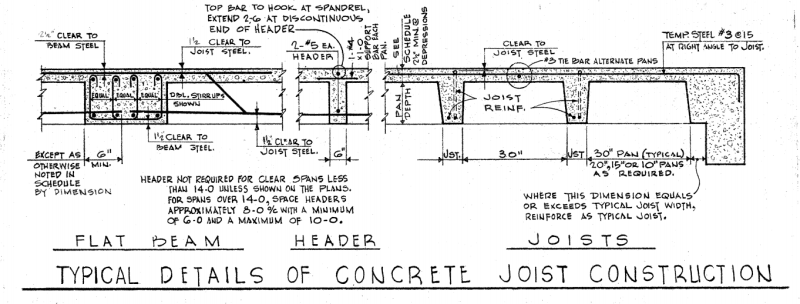
JAE pretty much has this, the layout starts from one side with the pans, this is generally a "one-way" system with some limited connections between them in the perpendicular direction (usually one in a 20' span, more in longer spans, sometimes reinforced with a #4 on the bottom).
Generally one preferred to keep the beams (girders if you'd rather of it it's after 3 pm in Paris), in the wider rather than deeper in the perpendicular direction so the formwork was all set at the same depth. (This is contrary to the current "use a flat plate as much as possible" and avoid beams as much as possible, but if you must, make them deeper than they are wider so long as the reinforcing fits approach).
Joists might suggest an older design as two way slabs started in around 1906 and onward, in the "builder's risk" sense, and though they didn't get the math right until the 1971 code. Anyway.
As to the "makeup" dimension on the one end, it's analogous to some Architects who can't be bothered to fit the dimensions of the modules they use, i.e. Masonry walls that are 13'-2" high, 14'-3" long and whatnot versus 8" increments for normal masonry construction. Or if you had roof trusses at 24" on center and the building is 24'-5" you've got an extra truss in there somewhere.
Alternately, the pan is usually 20" or 30" and the joist width is somewhat selected by the engineer designing them, 4", 5", 6" and the like (speaking extemporaneously here I'm not looking at the tables). They also made tapered end pieces if you had shear problems at the joist/beam (girder after 3 pm in Paris), or you widened the joists.
Usually there are CRSI tables involved, (or when I have to do evaluations of these, and it's been a while, I use the old CRSI tables, and they usually justify the design reasonably well, although Fling [a rather big name, so I gather, in Ohio, although now that I look, he's a
past President of ACI, ] and all his cohorts and spin-offs and people who worked for Fling tended to use a lot of moment redistribution so the beams can require a little manipulation of the moments via redistribution to make them work).
To make it a "full" dimension there's sometimes a filler pan or a makeup pan or some other term, it looks like the pans were standardized at some point, and prior to that, naturally, they weren't standardized.


This is "what I have" and it looks like it's a photocopy of something that was cut and pasted into a sheet of engineering paper (hence the "National" on the left margin), and then photocopied at least once more.
Google Image search can sometimes make progress with these, I've managed to trace the occasional unattributed figure using it.
Not convinced we can attach files anymore.
Also, terminlology varies through the country and one man's "footer" is another man's "footing" and so on and so forth, without bothering for the differences between the US, Australia, and the UK/Europe (Canada, if you ask me is a bit of a hodge-podge of US and UK) that's a bit of a blockage even now. We don't find current research from other countries when the search term we use is a "US only" term. Canadians seem to like "hogging moments" would be a good example. Even within a city or state the terms can vary.