Hi, I'm designing a lobby addition to an existing building in a non-seismic region using structural steel framing. Within our design group, we have been having a debate. Each of the columns is designed such that it is fixed at the base. Since the lobby is only one story, we are seeking to minimize the moments transferred to the column by "pinning" the tops of the columns to the beams/girders and moment connecting the beams/girder as a roof support structure so that it acts as a rigid diaphragm.
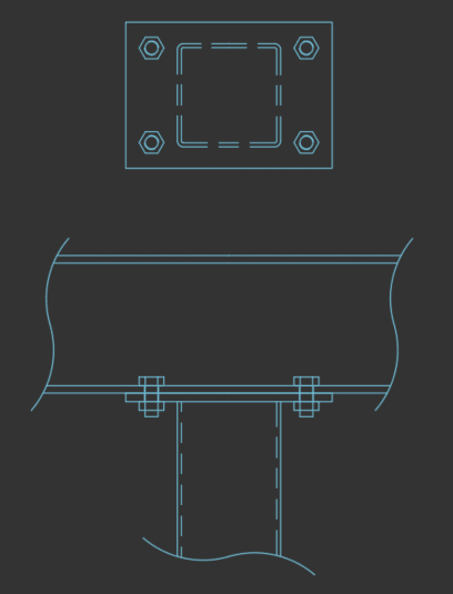
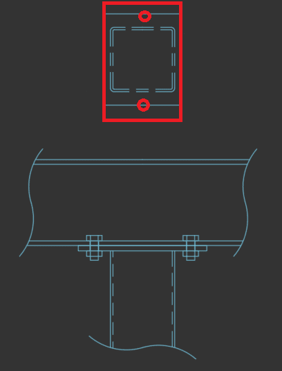
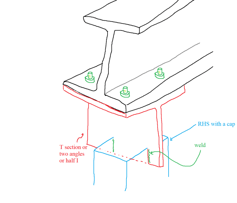
The structure has quite a large roof cantilever (10.5 ft) considering it's size, and the design is done such that the girders frame over the tops of the columns and extend to support the canopy. My question is, theoretically speaking, we have modeled the structure such that the columns are acting as cantilevers to support a rigid diaphragm roof structure, so the forces are transferred via shear at the top of the column and counteracted by the flexural resistance in the column which is transferred to the foundations, etc., but practically speaking, how can this connection be accomplished? If a cap plate is welded to the top of the HSS column and the bolts are spaced sufficiently far apart due to the column size and bolt gage of the girder itself, wouldn't the cap plate, if sized such that it transfers the compression from the roof loading to all 4 sides of the HSS, be sufficiently rigid that it would tend to transfer moment, despite not being modeled as such? I.e. The connection is modeled as a pin, but it is sufficiently stiff such that it prevents rotation in the girder to such a degree that the connection behaves as fixed.
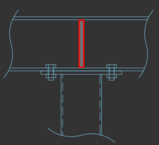
The way that I've been thinking about this problem up until now is similar to how I would approach a base plate and anchor design: If the plate is sufficiently thick that prying action is eliminated, then the column and plate will act rigidly and transfer moment. Therefore, if the cap plate is sized such that the the thickness exceeds t.np per equation 9-17 in AISC 15th edition, then the connection cannot help but to transfer moment because the column and cap plate behave rigidly. If this is the case, would this same behavior occur at the lower threshold of t.min per equation 9-19?
Am I thinking about this correctly? If not, what are we missing that needs to be considered in the design and/or modeling of this structure? If so, can a connection be designed such that moment is not transferred from the girder to the column? Does the moment transfer need to be considered in this connection?
Any help would be appreciated in considering this problem.
The structure has quite a large roof cantilever (10.5 ft) considering it's size, and the design is done such that the girders frame over the tops of the columns and extend to support the canopy. My question is, theoretically speaking, we have modeled the structure such that the columns are acting as cantilevers to support a rigid diaphragm roof structure, so the forces are transferred via shear at the top of the column and counteracted by the flexural resistance in the column which is transferred to the foundations, etc., but practically speaking, how can this connection be accomplished? If a cap plate is welded to the top of the HSS column and the bolts are spaced sufficiently far apart due to the column size and bolt gage of the girder itself, wouldn't the cap plate, if sized such that it transfers the compression from the roof loading to all 4 sides of the HSS, be sufficiently rigid that it would tend to transfer moment, despite not being modeled as such? I.e. The connection is modeled as a pin, but it is sufficiently stiff such that it prevents rotation in the girder to such a degree that the connection behaves as fixed.
The way that I've been thinking about this problem up until now is similar to how I would approach a base plate and anchor design: If the plate is sufficiently thick that prying action is eliminated, then the column and plate will act rigidly and transfer moment. Therefore, if the cap plate is sized such that the the thickness exceeds t.np per equation 9-17 in AISC 15th edition, then the connection cannot help but to transfer moment because the column and cap plate behave rigidly. If this is the case, would this same behavior occur at the lower threshold of t.min per equation 9-19?
Am I thinking about this correctly? If not, what are we missing that needs to be considered in the design and/or modeling of this structure? If so, can a connection be designed such that moment is not transferred from the girder to the column? Does the moment transfer need to be considered in this connection?
Any help would be appreciated in considering this problem.