Continue to Site

Eng-Tips is the largest engineering community on the Internet

Intelligent Work Forums for Engineering Professionals

  • Congratulations waross on being selected by the Eng-Tips community for having the most helpful posts in the forums last week. Way to Go!

Flatness of DMP in ISO 1

Status
Not open for further replies.

MaxSka9

Mechanical
Apr 23, 2024
9
After a drawing review concerning a print with a callout of flatness of a feature of size as pic related we were told by the manufacturer that it’s impossible to verify. Essentially that flatness of a derived median plane/feature of size is not possible and that we should specify one plane as datum A with flatness and the other plane to be parallel to A. That is an option for sure, but in my opinion flatness of DMP better captures the intent as I can live with some bending of the part as long as the derived median plane is within tolerance.

As both my company and our manufacturer use ISO, rule 1 does not apply here, so size does not control form. I know flatness of a feature of size is allowed in ASME 14.5 2009 and beyond, but I can’t seem to find anything about it in either ISO 1101 or ISO 12781. Neither if it’s allowed or if it’s prohibited, so we’re kind of stuck between a rock and a hard place.

Their inspection guy thinks I’m an idiot, and I think he’s an old geezer that just hates when “the new guy” use something different to what he’s used to.

If someone could settle this debate I would be eternally grateful
 
 https://files.engineering.com/getfile.aspx?folder=23b43778-c805-4a8d-a65e-37b8f5921fc7&file=IMG_0406.webp
Replies continue below

Recommended for you

From ISO1101:2017

The toleranced feature can be an integral feature or a derived feature.

For the purposes of this document, the terms “axis” and “median plane” are used for derived features of perfect form, and the terms “median line” and “median surface” for derived features of imperfect form. Furthermore, the following line types have been used in the explanatory illustrations, i.e. those representing non-technical drawings for which the rules of ISO 128 (all parts) apply.
 
Thanks greenimi, I already read the thread in question but I’m not sure how/if it applies in my situation with flatness of a FOS. I understand the difference between ISO and ASME in your thread, but not if it’s explicitly not allowed to use DMP flatness in ISO.

I found the same passage as you did in ISO 1101 but it’s quite unclear if this also applies to flatness. I read this passage as a general explanation of what the GD&T tolerances mentioned in ISO 1101 CAN apply to. Some only apply to an integral feature and not to a derived one and so on. Usually there’s multiple examples of proper usage of each symbol, but when it comes to flatness its only ever shown on integral surfaces.

My part is a sheet metal part (prone to bending) and what I’m interested in is simply to limit the median plane from becoming to curved. I could achieve that with a separate flatness and parallelism tolerance together with my dimension tolerance, but I’m quite hesitant to do so
 
OP said:
...Some only apply to an integral feature and not to a derived one and so on....


Not sure why it is not clear, as per 17.3 that the flatness could be applied to a derived feature.
Isn't it that in your case?

Please advise.


If you add the (E) symbol to the size, then it acts as ASME Y14.5 size limits act.

It is not impossible to determine this value, but it is difficult. To me it is much like the discarded ASME Y14.5-2009 symmetry, but without a datum feature reference. You need to come from both sides simultaneously to make opposing measurements and then compare the average of the deviations to the tolerance as measured from a nominally flat external surface or stand-in.

I'm sure in using a CMM those deviations will get a plane fitted through them and the measurements then re-evaluated to calculate some minimum, but with dial indicators and a surface plate, one may have to adjust the part until it is either proved satisfactory or the inspector gives up.
 
Also, and really curious - what solid external part does the median surface of this part come in direct contact with?

Since it is sheet metal, does the thickness vary so much from location to location that the flatness variation on one side fails to match the flatness variation on the other side such that parallelism would be a factor?
 
@greenimi I will have to check that out first thing in the morning as I’ve gone home for the day and have no access to the ISO standards at home unfortunately.

@3DDave I’m aware of the envelope symbol as we use it quite often on holes. That could be one alternative, but usually our suppliers and our own procurement team thinks adding the (E) symbol immediately makes the part 10 times more expensive to makes while in reality it does not.

Well as you’ve probably figured out the median plane does not mount to anything. I have no CAD acces at home, so sadly I can’t make a similar part to show you, but I could try to describe it. ; The part consists of a sheet metal slab about 5mm in thickness with 2 clearance holes going through the entire part. If I flip the part over it looks exactly the same and there are no distinguishing features that makes you able to identify the surface the manufacturer suggests I use as datum A from the parallel surface on the other side. The part is welded in the middle of a kind of slot on the mating part.

My idea was to use the feature of size that the holes are perpendicular to as datum A and control its form with the DMP flatnesses tolerance. I would then use the holes as datum B-B and make them perpendicular to A. The outer rectangular profile would be controlled by a profile tolerance to A|B-B. Kind of like this picture attached.

I could add some sort of a chamfer or similar to clearly distinguish one surface from the other. And I might just do this if it’s the only way, but I would just like to know if it’s “illegal” to specify my parts as I have now and if it’s totally impossible to make and inspect. As this is a modification of a design that already exists I’m quite constrained in what I can and can’t redesign, and as always it needs to be done yesterday.

As a former machinist I’ve seen similar callouts before and we were always able to make it to spec and quality managed to inspect it. I would just make the parts in two setups, one where I make one surface+ the holes then flip it around and face to opposite surface. Or if I was in a 5axis I would machine the feature of size (the part “standing on its side”) probe to find the derived median plane and make the holes perpendicular to it. Then I would mill the outside profile accordingly, leaving a small tab so I could “break it off” and just deburr the small edges left behind.
 
 https://files.engineering.com/getfile.aspx?folder=5541c584-f306-4a50-9644-430963de68ad&file=IMG_0409.webp
Use two position tolerances, one to each face. No rule against it. Likewise the profile tolerance.

If anyone bitches about it, add some feature that provides a unique orientation.

Since one cannot fixture to the median lumpy center plane to drill the holes, it makes little sense to use it as a datum reference.

 
Well, here’s the update.
@greenimi you were absolutely correct. I even contacted a guy I know at the ISO committee and they confirmed in this instance ISO and ASME work the exact same way when it comes to flatness of DMP.

@3DDave we came to the conclusion today to move the holes up one level to the assembly, circumventing the need for datums on the part in question. We will just drill the holes after welding, which is better anyway to ensure proper alignment.

BUT if someone else ever wonder how ISO and ASME differ when it comes to flatness of a derived median plane we now know that they’re the same [bigsmile]
 
MaxSka9,
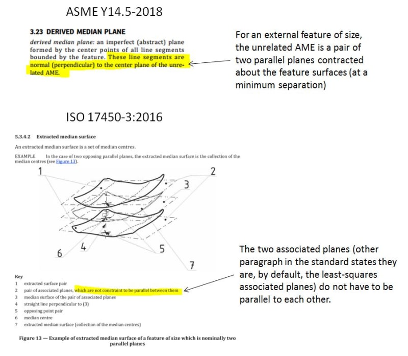
DMP flatness is not the same in ISO and ASME. The difference is in the way the median plane is established from the as-produced geometry. It's not a big difference but it exists.
 
@pmarc Well haha I stand corrected then. Could you give an example of how they might differ?

I understand the difference between ISO and ASME when rule 1 is applied when it comes to extracting planes or axis from surfaces and features of size

But doesn’t flatness of a derived median plane nullify/override rule 1 anyways?

I ways mainly happy I was right in that it was even possible in ISO at all haha.
 
pmarc said:
DMP flatness is not the same in ISO and ASME. The difference is in the way the median plane is established from the as-produced geometry. It's not a big difference but it exists.

I am curious too about the subtle differences.....

Thank you pmarc

 
MaxSka9, greenimi,
The illustration below is aiming to show the difference. First difference is in naming - Derived Median Plane in ASME vs. Extracted Median Surface in ISO. Let me know if it helps.

To answer the other question: "But doesn’t flatness of a derived median plane nullify/override rule 1 anyways?"
Yes, in ASME the DMP flatness always overrides Rule #1 and so if one wants to control the DMP flatness within Rule#1 an additional trick needs to be used to accomplish that.

capture_cccc_ohv7qo.jpg
 
It occurs to me that it's not the Unrelated Actual Mating Envelope as that cannot be determined until the feature is brought into contact with the Actual mating parts.

It's a Theoretical Unrelated Mating Envelope which is a stand-in. TUME.

Wait.

It's an Approximated Theoretical Unrelated Mating Envelope because of imperfections in the inspection equipment - ATUME!

The question I have is this - what function is used in any FEA program to understand the behavior of the part based on the derived median plane (hmm, it's not planar) or extracted median surface (score one for ISO making a sensible term, but they apply it to a plane that they call a surface)?

Since this is a critical control with a lot of thought put into details of how to measure it, there must be examples showing real-world implications.
 
pmarc said:
...so if one wants to control the DMP flatness within Rule#1 an additional trick needs to be used to accomplish that....

pmarc,

flatness |0 MMC|
flatness | tolerance|

I think I learn it from you (pmarc) and since my memory is not that great, I am asking you, again, if it is correct or I missunderstood you?

 
greenimi,
Yes, you remembered that well.
 
Status
Not open for further replies.

Part and Inventory Search

Sponsor