jsu0512 said:
Hi BAretired,
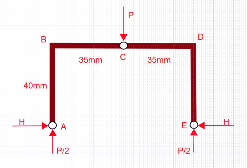
The height is 40mm. How does the the bolt shear is calculated with the height of vertical leg? I appreciate for your response.
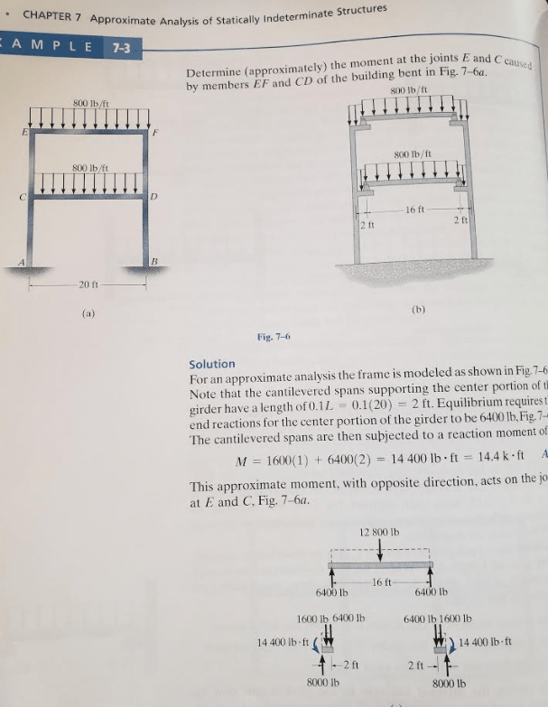
The structure is indeterminate, which means that to solve the problem elastically, one must either have a 2D frame program or tables. The curves at the bend points would also need to be taken into account for a thorough analysis.
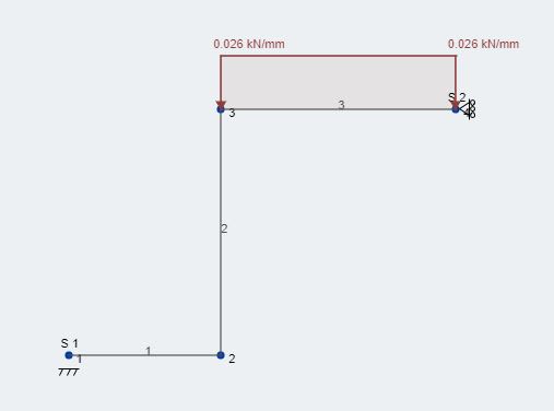
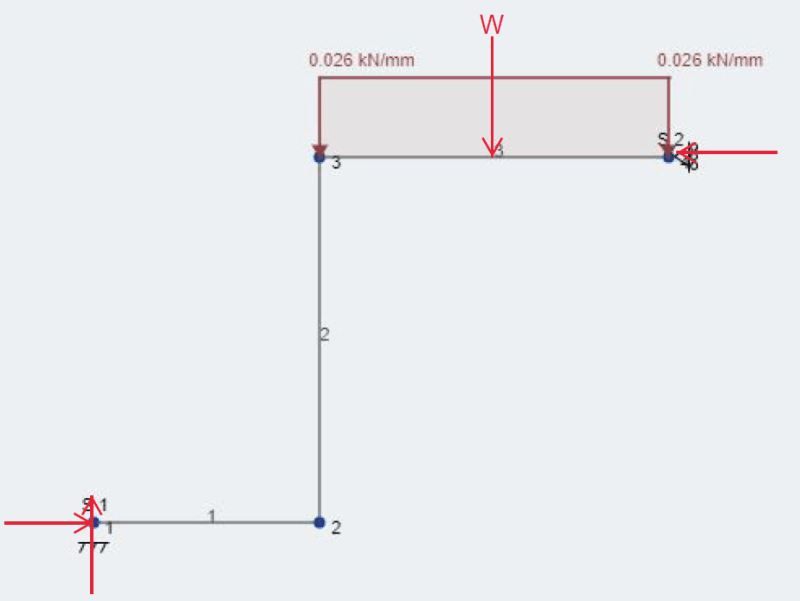
The bolts add several degrees of indeterminacy to the problem. If, instead of bolts, you assume the clip is supported on a flat surface with a pin under one wall and a roller under the other, the problem becomes determinate. In that case, the load will cause the supports to spread apart which they can do freely. In that case, the top beam cannot develop moment at the ends, so it spans as a simple span with concentrated load of 2kN at midspan. The failure load would be P = 7.5kN as shown in my earlier post. To be consistent with normal practice, a phi factor should be included to account for unknown properties of the material. In Canadian practice, a phi factor of 0.9 is normally used, giving a calculated failure load of 6.75kN instead of 7.5kN.
In my judgment, the problem, including bolts each side, tightened down to prevent rotation, is closer to a rigid frame fixed at the bottom of each vertical wall; closer, but not exactly correct. So I tend to believe that the failure load is likely closer to 15kN or, with phi factor included, 13.5kN.
Like many engineering problems, more precise calculations can be made. The question is, does it really matter in this case? If the expected maximum load is 2kN, then either solution would seem to provide an adequate solution without going into further refinement.
BA