Eng-Tips is the largest engineering community on the Internet

Intelligent Work Forums for Engineering Professionals

Flitch plates for wood balcony cantilever beams

Status
Not open for further replies.

anchorengineer

Structural
May 26, 2009
88
0
0
US
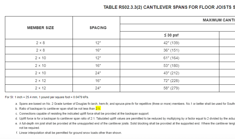
We have a project where the existing 8ft cantilevered triple LVL beams for a balcony have deteriorated. These are main beams and the balcony joists are perpendicular to these. We want to cut the main beams at the face of the building and install flitch plates to replace their strength. We will extend the flitch plates back into the building and use pressure treated blocking to fill the space between the plates on the exterior. The rule of thumb is to extend the inboard cantilevered sister beams (flitch plates in this case) 2x the length of the cantilever. The balcony is 8ft wide which puts us 16ft into the building. Does anyone know of a more precise method of analysis? We also thought about extending the plates the distance until the moment due to the cantilever equals zero, but since we have resisting NE snow and it's big enough for 100 psf LL it is long and seems extreme. Do we focus mainly on uplift deflections? Thoughts?
Thanks!
 
Replies continue below

Recommended for you

An interesting use case for flitch plates. I don't think you need to consider the rules of thumb for cantilever and backspan ratios as much as you need to resolve the moment from the flitch plates into the existing LVL beam and be satisfied that the connection forces you are imposing on the LVL are appropriate. I'm not sure what the spacing of these main beams are, but the connection forces seem like they would get pretty reasonable for steel side plates at about 8' backspan.
 
There is no rule of thumb on cantilevers. Not sure where all that 2:1 shit that is thrown around ever came from. Run it in a beam program and check all the normal stuff. I would try to keep it at 20 ft. long as that is a standard material length. You might consider welding a bearing plate on the flitch at its fulcrum point as the connection demand there may be hard to manage with fasteners alone.
 
As I understand it, the 2:1 is for the joist member proper and is a sensible way to prevent overturning without a lot of connection fuss. As ryaneng mentioned, this is basically just a moment connection between your new cantilever and the old backspan. Your overlap distance can simply be predicated upon the design of that moment connection.

Isn't this going to be a nightmarish thermal break?
 
anchorengineer said:
This is a rehab of an existing multifamily structure and there is no existing thermal break.

Sorry, poor choice of words. What I meant to say is that your steel plates will create nightmarish thermal bridges between the outside of the building and the inside. Condensation problems and all that jazz.
 
KootK said:
As I understand it, the 2:1 is for the joist member proper and is a sensible way to prevent overturning without a lot of connection fuss.

meh, I disagree. Every situation is different.
 
XR250 said:
meh, I disagree. Every situation is different.

What's to disagree with? The 2:1 is undeniably a reasonable way to limit uplift. If you wanna math out something more aggressive, go to town. Obviously, no rule of thumb applies to every situation. One. Must. Keep their wits about them...
 
In regards to the 2:1 backspan to cantilever ratio: that's what the International Residential Code says to use in it's prescriptive tables.
IRC_Cantilever_Table_fralpf.png

So if you're Joe contractor, that's what you use. If you're an engineer, design something that works.
 
KootK said:
What's to disagree with? The 2:1 is undeniably a reasonable way to limit uplift

It is a way. 2.5:1 would limit it even more.

SandwichEngine said:
So if you're Joe contractor, that's what you use. If you're an engineer, design something that works.

Exactly.
 
Thanks for all of the replies!
-The existing cantilever beam is (3) 18" LVL's. The cantilever is 8ft with a 10ft tributary width. The inboard length of the beam is 24ft and extends to in interior wall. this beam has a detail for connecting all three layers making it composite. The deterioration of this beam occurs mainly towards the edge of the balcony (away from the face of the building) due to poor drainage.
-My main concern is transmitting the moment into the interior portion of the beam without creating unacceptable uplift of the floor.
 
XR250 said:
It is a way. 2.5:1 would limit it even more.

With that, I suspect that you're critiquing what seems to you to be the arbitrary choice of 2X vs some other multiple. I don't believe that it is arbitrary but, rather, based upon:

1) The traditional factor of safety of two for overturning and;

2) The assumption of uniform load across the entire span.

So it's likely not arbitrary. Or, at the least, no more arbitrary than most things in engineering. And, in my opinion, it's good practice, even for engineered designs. I normally try to do this, or something close to it, unless there's a good reason for me not to.

I feel that the folksy, rule of thumb stuff that has been bequeathed to us by our forbearers is bloody awesome and I try to stick with it whenever I can.

OP said:
My main concern is transmitting the moment into the interior portion of the beam without creating unacceptable uplift of the floor.

You'll have the same uplift tendency at the far end of the beam back span regardless of how you set up the reinforcing scheme (other than, perhaps, the weight of the cantilever).
 
Regarding uplift deflection, you're not actually changing the loading by doing the flitch plate. If the existing LVLs were designed properly, they already took the deflection into consideration. If anything, you're incidentally and slightly reducing it since the flitch plate will add some stiffness to the sistered portion.
 
KootK said:
1) The traditional factor of safety of two for overturning and;

2) The assumption of uniform load across the entire span.

Lets face it, the most common load case is the cantilever loaded up with only dead load on the main span.

For me, every design is unique which balances material usage, cost and connection demand. For a standard wood framed balcony with a 5 ft. cantilever, a 1:1 backspan typically works fine. The connection demand is only about 250 lbs at the end and it saves 5 ft. of lumber in every bay. In contrast, if I am cantilevering a 2nd story 24" from the first story, and I am sistering the joists, I will go back farther as the connection demand will be high and it will help reduce the sag as the main span will be stiffer.
As I see it, 2:1 is pretty arbitrary - just like a lot of things in the building code (6 ft. O.C. anchors, collar ties 1/3 down from the ridge)
 
XR250 said:
Lets face it, the most common load case is the cantilever loaded up with only dead load on the main span.

Sure, but then that's just another -- and possibly better -- way to justify the rationality of the method. With live load on the cantilever only, this would allow one to have a live load 3X the dead load without producing uplift at the far reaction of the back span. So maybe 10 PSF reliable dead and 30 PSF live. Pretty reasonable, even if the goal were to just keep uplift modest rather than prevent it outright.

XR250 said:
For me, every design is unique...

Agreed but, again, I'm not saying that you shouldn't toss out the 2X back span and design as you wish. What I am saying is:

1) The 2X thing is good, folksy construction wisdom that had a reasonable range of application in the past and has a reasonable range of application in the present.

2) Because of #1, the 2X back span rule of thumb deserves a little respect and ought not be thrown out with the bath water wholesale.

XR250 said:
As I see it, 2:1 is pretty arbitrary - just like a lot of things in the building code (6 ft. O.C. anchors, collar ties 1/3 down from the ridge)

I don't feel that either of those things is arbitrary either. Rigorous, no; arbitrary... also no.
 
anchorengineer said:
Does anyone know of a more precise method of analysis?
The more precise method of analysis is to analyze it. I take the rule of thumb to be an easy-to-understand first step.

It may come down to the capacity of the connection between the steel and the existing LVL. As you iterate toward a solution, you can start with a 16' backspan and determine your connection. If you want to use fewer or smaller fasteners, then you make the backspan longer. Then check the load imparted on the original LVL, which I'd expect to be okay.

If only a small portion of the original LVL is deteriorated, I'd consider leaving as much of the original in place as you can, so there's more to anchor to.

anchorengineer said:
... it is long and seems extreme.
Also, I wouldn't characterize it as 'extreme' to have a longer backspan, just the opposite. The shorter the span, the more 'extreme' the solution, because you rely more on the fasteners.

 
Others have beat up the structural solution pretty well. Is there an architect involved in this repair? Make sure this thing is flashed properly. While I agree with kipfoot's suggestion to keep as much of the existing LVL as possible, LVL's aren't made for outdoor uses (with the lonely exception of Pacific Wood Tech's treated LVL, a feat I don't believe anyone else has duplicated yet). So flashing tape , breathable cladding, etc. will need to be considered and applied. Also consider how moisture might get trapped between the steel and the LVL outside. Not knowing much about the climate and details of the building, I'm not sure how bad this is going to be for your application.
 
Status
Not open for further replies.
Back
Top