Continue to Site

Eng-Tips is the largest engineering community on the Internet

Intelligent Work Forums for Engineering Professionals

  • Congratulations SSS148 on being selected by the Eng-Tips community for having the most helpful posts in the forums last week. Way to Go!

Flow Switch in Pump Suction

Status
Not open for further replies.

DGrayPPD

Mechanical
Feb 2, 2017
300
Capture_mcvrdq.png


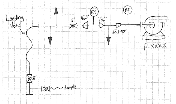
Process and E&I are developing P&IDs for an upcoming project. The picture I've attached shows the preliminary drawing they have come up with. As I'm sure we all know by now, concentric reducers should not be used in pump suction lines unless the pump is a top suction pump, which this one is not. I've brought this point up to them along with discussing cavitation, but as of now they are not wanting to change what they have come up with. Their reasoning being the line size is too small for the flow switch insertion into the pipe and they want the flow switch to protect the pump (obviously).

Before I go back and argue some more, I was looking for some reinforcement that I should continue this argument and look for an alternative solution.

The pump will be used for offloading tanker trucks with refinery grade propane and sending it off to bullet storage tanks.
 
Replies continue below

Recommended for you

I believe you are justified in continuing the argument - from what I see, there's a possibility in vapor accumulating in the segment containing the flow switch. Unless there is some nuance with pumping liquid propane that I am not aware of, I agree with your position as stated.

Any chance the flow switch segment could be located on vertical without decimating your NPSHa?
 
Thanks for the backup KoachCSR.

I do not foresee there being any vertical piping on the suction to locate the switch.
 
DGray,
1, On your sketch there are three "branch" line indications with arrow heads. What are these please?
2. What is the purpose of the Flow Switch?

Sometimes its possible to do all the right things and still get bad results
 
A good practice to maintain the higher NPSHa with the minimum pressure drop in the pump suction line. IMO, the FS for the pump shutdown may be located at the pump discharge, so it won't cause any turbulence the pump, or interfere with the pump start-up at the zero flow condition.
 
Pennpiper,

The two bottom branch lines tie together and run to the flare.

The top branch line is a bypass that runs to the pump discharge in case the tanker truck pumps are used.
 
Thanks mk3223, I think that might be my suggestion.
 
While this is not the topic of this thread, presume you've got the customary emergency dry break coupling some where along this suction hose. Agree with others concentric reducers are not preferred here and that the FS should be moved to pump discharge.
 
Also throttling valve and sample valve should be at pump discharge along with the FS. If sample valve where you show it located, opened with the pump running it will draw in air. Throttling valve should be at pump discharge to not cause cavitation if throttled. Make sure hose type is rated for vacuum service. Provide vent valve at all high points of discharge piping and drain valve at all low point.
 
Status
Not open for further replies.

Part and Inventory Search

Sponsor