Continue to Site

Eng-Tips is the largest engineering community on the Internet

Intelligent Work Forums for Engineering Professionals

  • Congratulations SSS148 on being selected by the Eng-Tips community for having the most helpful posts in the forums last week. Way to Go!

Footbridge built of a deck under a truss with no bracing or diaphragm at the supports? 9

Status
Not open for further replies.

Logan82

Structural
May 5, 2021
212
Hi!

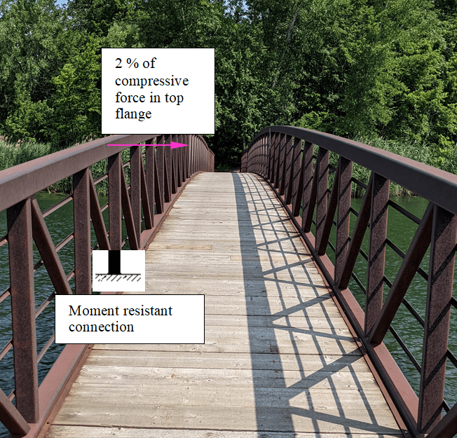
I have seen several footbridges with this configuration:
PXL_20210722_150608813_gsqnge.jpg


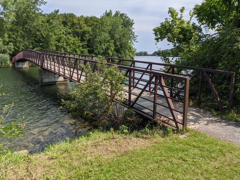
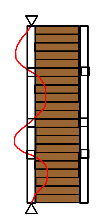
I am wondering how such footbridge configuration are allowed considering that there are no diaphragms or bracings at the supports, like this:
2021-08-21_13_28_22-PXL_20210722_150608813.jpg_-_Windows_Photo_Viewer_wgkny5.png

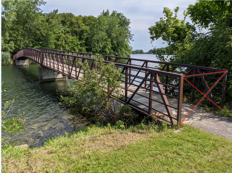
Note that I am sure these are allowed considering that there are many footbridges like this. I am trying to figure out how to justify that through code or calculation.

To have diaphragms at the supports like what I have drawn, it implies that the footbridge deck is on top of the steel truss structure.

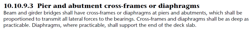
Diaphragms and bracings are required at the supports according to CSA S6.
2_emfcqq.png


This is a follow-up of this thread:
 
Replies continue below

Recommended for you

Logan82:
They are saying, in 10.10.9.3, that a good share of the lateral loading occurs from activity on and around the deck and deck level. Thus, when the deck is up at the top chord, you need some x-bracing or a diaphragm at the supports to get this loading down to the bearing level and to keep the whole system stable laterally. When the deck is at the bottom chord, those same lateral loads go directly into the bearing system, so at most, you have a cross beam, or some such, btwn. the two bearings. There has been considerable discussion over the years about the stability of the top chord members of bridges like you show. As you say, they do seem to work (they do work when properly designed and built), there are certainly lots of them out there.

 
The AASHTO specs for pedestrian bridges address the treatment of the top chord.
 
Those verticals and diagonals are not pure pins. The are semi rigid or rigid moment connections. If this wasn't the case then leaning against the top cord railing won't cause it to rotate around the axis of the bottom chord. That stiffness is sufficient to reduce the effective length of the top chord significantly.

(I recently designed a truss like this. The effective length calculated through buckling length calculation reduced from 20m down to about 3m. The spacing of the verticals was 1.1m. I ended up not going ahead with the design. It was simple to just have an underslung truss braced in a manner like you've shown with separate handrails.)
 
Thank you all for your answers!

human909 said:
That stiffness is sufficient to reduce the effective length of the top chord significantly.
Are you talking about this length that can be reduced?
2021-08-21_21_19_54-PXL_20210722_150608813.jpg_-_Windows_Photo_Viewer_x2gqei.png


If so, how can the stiffness reduce the effective length? I would have thought that only a crossframe or diaphragm at some interval would been sufficient to reduce the effective length, like this:
2021-08-21_21_29_10-Document1_-_Microsoft_Word_Product_Activation_Failed_xqefak.png


Did you take 2 % of the compressive load and verify if the moment connection at the bottom chord can resist that?
2021-08-21_21_39_36-Document1_-_Microsoft_Word_Product_Activation_Failed_szozxl.png
 
Logan, the U-frame made of the vertical posts and the cross beam under the deck results in a lateral stiffness at the top chord. It will be less stiff than your cross bracing but adequate to increase the buckling capacity (= reduced effective length). In the image, there is a stiffness which results in the effective length being the distance between braces and making the bracing stiffer doesn't increase capacity further. At lower stiffness, the half-sine length of buckling is longer than the distance between braces but still increases buckling capacity compared with no bracing. This is how U-frames work (aka pony trusses).

20210822_115100_rnrul9.jpg


From Yura's paper "Fundamentals of beam bracing".
 
As others have noted, the superstructure is a pony truss, not a beam or girder bridge, so the quoted portion of the spec is not applicable. Beams and girders are below the deck. Lateral loads (from wind, etc.) applied in the span will be carried by the deck (the horizontal diaphragm) to the ends of the spans. The lateral load from the tributary length of the bridge must be carried from the deck through the bearings to the substructure. If the girders are between the deck and the bearings, crossframes or diaphragms (and stiffeners) are needed transfer the lateral shear force to the bearings.

In the case of the pony truss bridge shown, the deck is not significantly above the bearings, and the floorbeam running transverse at the bearings transfers the lateral shear. The area of the truss subjected to wind load is also significantly less than that of a girder.

Rod Smith, P.E., The artist formerly known as HotRod10
 
The compression chords of open bridges may be modelled as compression elements with lateral supports provided by vertical struts and diagonals.

BS EN 1993-2:2006 ( Eurocode 3-2 ) appendix D Table D.3 gives the formulas for stiffness of the lateral supports which may be used to determine .

The excerpt of the same page attached ;

stiffness_of_lateral_supports_qtgxbu.jpg
 
Thank you all! The information you provided me was enlightening.
 
Human909 said:
(I recently designed a truss like this. The effective length calculated through buckling length calculation reduced from 20m down to about 3m. The spacing of the verticals was 1.1m. I ended up not going ahead with the design. It was simple to just have an underslung truss braced in a manner like you've shown with separate handrails.)

what procedure did you use for this determination, if I may ask?

Rather than think climate change and the corona virus as science, think of it as the wrath of God. Feel any better?

-Dik
 
Logan82

As other repliers have pointed out, your upper horizontal "hand rail" beam is laterally supported against buckling by the lateral stiffnesses of the tips of the U-frames.[ ] This stiffness is finite rather than infinite, but it draws its effectiveness from the fact that there are multiple such stiffnesses at regular intervals along the run of the bridge.

If the lateral support stiffness provided by each frame is K [in units F/L] and the U-frame spacing is S [units L], you can convert the overall lateral restraining stiffness to a value of K/S [units F/L²] applied continuously along the handrail.[ ] This converts the problem to that of continuous beam supported on an elastic foundation, for which there are "standard" formulae for the buckling load.[ ] See, for example, Roark's Formulas.[ ] In my fifth edition of Roark it is Table 34, case 4, in the chapter "Elastic Stability".[ ] However there is an error in the formula he gives, where the exponent applied to pi in the denominator of the second term should be 4 rather than 2.[ ] See Roark's reference #1, Timoshenko, for evidence of this assertion.[ ] (I notified the publisher of this error, and I believe it was fixed at some stage.)

Making the further simplification that the handrail is near enough to infinitely long, an assumption that is easily — and should be — confirmed/negated, Roark's (ie Timoshenko's) formula (after the above correction), reduces to
Pcrit =2*Sqrt(KEI/S)
The corresponding "half wave length" of the buckled shape is
pi*(EIS/K)^(1/4)
and this should be checked to verify that each half wave includes enough U-frames for the "continuous lateral support" assumption to be appropriate.
 
Hi Denial, interesting! Looking in the 7th edition, it looks like they did the modification you were talking about with pi:
1_s2zzvi.png


Denial said:
The corresponding "half wave length" of the buckled shape is
pi*(EIS/K)^(1/4)
Where did you get this formula?

In Roark, it says: "both ends hinged". It implies that the end conditions of the top chord are pinned like this:
(view from the top)
3_phru0b.png

How do you make sure the U frames at the ends of the bridge are sufficiently stiff to make sure that the tips of the U are restrained in the horizontal plane?

Another question: say that there are no intermediate U frames, the only U frames are the supports. The effective length = the total length. Would you say there would be a minimum stiffness required for the U frames at the supports? If so, what would it be?
 
@human: Thanks. I've copied all 6 'episodes'... some lite reading for next week or so. The website looks great. Even the commentary is top drawer. I've copied it to a docx file (the format and formulae were retained) and then to my *.pdf printer (also retained). I can then edit the pdf document to highlight important stuff... do it often.

Rather than think climate change and the corona virus as science, think of it as the wrath of God. Feel any better?

-Dik
 
How costly is Spacegass?

Rather than think climate change and the corona virus as science, think of it as the wrath of God. Feel any better?

-Dik
 
dik said:
@human: Thanks. I've copied all 6 'episodes'... some lite reading for next week or so. The website looks great.

No problems. In case you were wondering the thread that was referred to at the start which inspired the series of posts was this one:

Not nearly as concise as Agent666's six part series. But there was some interesting discussion there.

Logan82 said:
How do you make sure the U frames at the ends of the bridge are sufficiently stiff to make sure that the tips of the U are restrained in the horizontal plane?
In reality you might not be able to or your might choose not to pin them. In which case you'll need to consider how infinitely long you need it to suit the assumption. For a long bridge it will unlikely make a difference to the buckling behaviour. For a short bridge it will.

dik said:
How costly is Spacegass?
Around $3000-$4000AUD so about $2000 to $3000USD. That is a once off cost for the basic analysis and buckling package. If you want the continuing upgrades then there is a yearly contract fee. There are also many other modules eg connection design and member design to various international codes. Other concrete items too, though I'm not sure if it is used as much for concrete design as steel.

The software is most popular in Australia/NZ as that is it's original target market. But it has other customers in other localities. The software still has an interface that is more like something from Windows 3.1. But it is effective and does most things you need in a easy way and there isn't too much hidden in the black box as it refers back to the codes in any design checks.

30 day free trial if you wanted to check it out. I think you need to email them, the link will be on the website.
 
Logan82

Thanks for confirming the correction.[ ] I have wondered about that from time to time.

Where did I get that simple Pcrit formula?[ ] I derived it for myself as an academic exercise many years ago.[ ] ("Sad", I know.)[ ] When the pages of algebra (since lost, when I ceased employment) eventually spat out that elegant result I was pretty confident I had got it right.[ ] It was when I was trying to confirm the result that I realised Roark's formula had that transcription error.

However you should not trust me on that formula, and you don't need to.[ ] You can get to the result from the pair of formulae Roark gives.[ ] Just let the overall length head off to infinity and things simplify.[ ] (It's odd how this often this happens:[ ] there's something quite magical about aleph-1 sometimes.)

Comments on your query re the "ends".
1. You raise a "practical" question, and I'm not very good with those.
2. Under my assumption of infinite length they are quite a long way away.
3. If the overall bridge is "simply supported" then the top chord will have a low compression at those ends.
 
Status
Not open for further replies.

Part and Inventory Search

Sponsor