Robert Clark
Aerospace
- Sep 1, 2021
- 19
Well known examples of the force produced by pressurized water exiting a pipe:
JetLev Water Propeled jet Pack.
Hovering Car.
I need to calculate the maximum for the thrust produced when the hose or pipe is bent rearward.
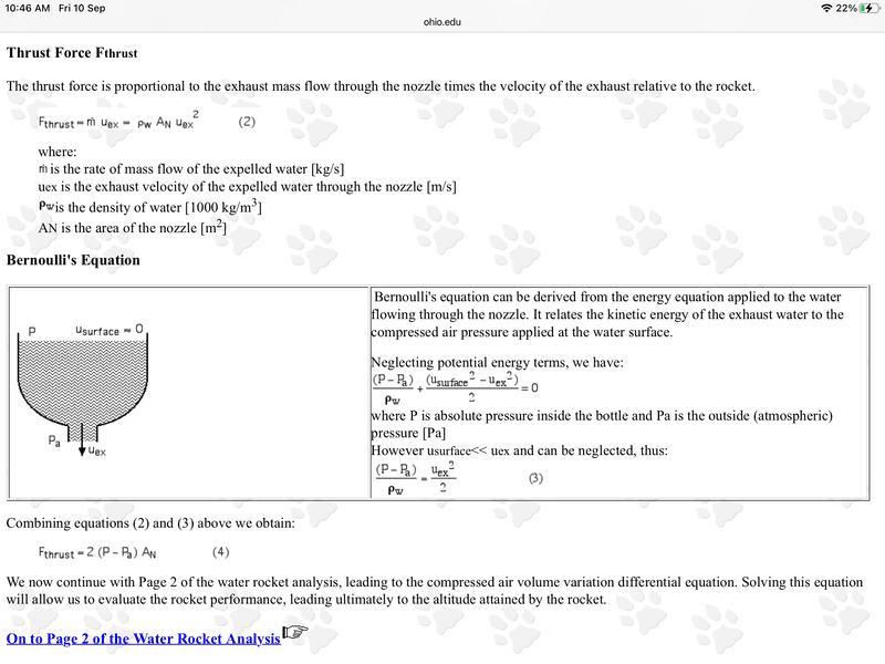
Since this is similar to the case of a water bottle rocket, the guess is it should be the same as that case:
The thrust force is:
F = 2*(P - P₀)*An,
Where P is the pressure in the pipe, P₀ is the ambient air pressure, and An is the area of the nozzle.

Note the extra factor of 2 there. An odd aspect of this formula is that it would appear that you could just increase the thrust by making the nozzle size larger.
However, note in the derivation you need the cross-sectional area to be small enough on exit so that, by the Bernoulli principle, the exit velocity would be large. So making the exit area larger would obviate the argument used.
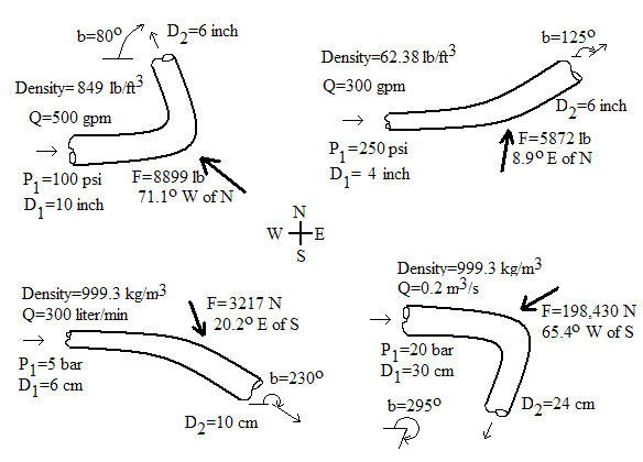
Here is the issue though. Another formula used for calculating the force required to hold a pipe in place because of the force produced on the bend due to the momentum of the water flow may, or may not, give a different answer.
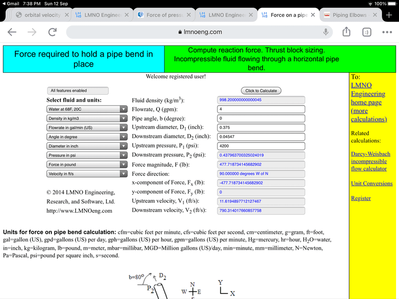
See the calculations here:

Equations for force on pipe bend calculation
The equations used in our calculation can be found in nearly any college level fluid mechanics textbook (e.g. Munson et al., 1998) or fluid mechanics reference handbook. The force equations are based on linear momentum conservation. P₂ is computed using the Bernoulli Equation, which assumes negligible friction loss around the bend.
Subscript 1 is upstream of bend; Subscript 2 is downstream of bend; Subscript x is x-component of force; Subscript y is y-component of force. For a pipe bend in the horizontal plane where friction effects around the bend are negligible:
Fx = -P₁A₁- P₂A₂ cos(b) - d Q [V₁ + V₂ cos(b)]
Fy = P₂A₂ sin(b) + d V₂ Q sin(b) F = (Fx2 + Fy2)1/2
Q=VA, A=π D2 / 4
P₂ = P₁ + d (V₁2 - V₂2) / 2
Variables
To use the equations above, a consistent set of units must be used. The variables below show the SI (System International) units for each variable. Our calculation allows a variety of other units with the conversions made internally within the program.
A=Pipe flow area (m2)
b=Pipe angle shown in the figure above (valid range is 0 to 2π radians or 0 to 360o)
d=Liquid (or gas) mass density (kg/m3)
D=Pipe diameter (m)
F=Resistive (reaction) force (N)
P=Gauge pressure (N/m2, relative to atmospheric pressure
For the scenario we are considering, the hose is bent backwards, so the angle b in the formula is 0. So,
Fx = -P₁A₁ - P₂A₂ - d Q [V₁ + V₂]
Fy = 0
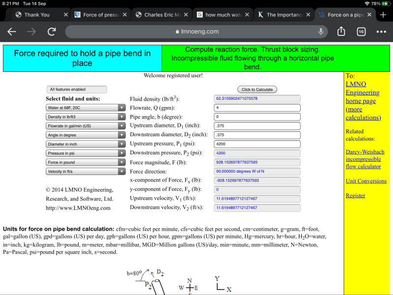
The minus sign is because the formula is calculating the force required to oppose the force on the pipe. Let’s look at the case, where the cross-sectional area is not changed. Then, it would appear, P₁ = P₂, and A₁ = A₂, V₁ = V₂. Then Fx = - 2PA - 2dQV.
For the scenario we are considering the pressure is high, but the speed V of the flow is low. Then the calculated force would be approx. Fx = -2PA, i.e., the force by the water on the pipe is Fx = 2PA.
The problem is this would be much larger than the water rocket formula since it uses the full cross-sectional area of the pipe, not just that of the nozzle.
Perhaps the problem is for the formula to be correctly applied what should be done is is for the exit pressure P₂ we should use the pressure of the ambient air, much smaller than the initial pressure in the pipe of P1. In that case the P₂A₂ term is approx. 0, so can be neglected. But what should we take for V₂?
By the Bernoulli formula for P₂ being greatly reduced that should ramp up the velocity V₂. Then V₂ would be much larger than V₁ and we can neglect dQV₁, so Fx = -P₁A₁ - dQV₂. We still have that force being much larger than the water bottle rocket case because A₁ is the area of the full hose/pipe not that of a nozzle.
So what is the real force being produced? This is something that can be tested for pressure washers. You would bend the hose backwards, and measure the force on the hose tending to force the hose away from you.
Pressure washers are provided with various nozzle sizes. The force produced should also be measured for all the nozzles provided as well as for the case with no nozzle.
Robert Clark
JetLev Water Propeled jet Pack.
Hovering Car.
I need to calculate the maximum for the thrust produced when the hose or pipe is bent rearward.
Since this is similar to the case of a water bottle rocket, the guess is it should be the same as that case:
The thrust force is:
F = 2*(P - P₀)*An,
Where P is the pressure in the pipe, P₀ is the ambient air pressure, and An is the area of the nozzle.

Note the extra factor of 2 there. An odd aspect of this formula is that it would appear that you could just increase the thrust by making the nozzle size larger.
However, note in the derivation you need the cross-sectional area to be small enough on exit so that, by the Bernoulli principle, the exit velocity would be large. So making the exit area larger would obviate the argument used.
Here is the issue though. Another formula used for calculating the force required to hold a pipe in place because of the force produced on the bend due to the momentum of the water flow may, or may not, give a different answer.
See the calculations here:

Equations for force on pipe bend calculation
The equations used in our calculation can be found in nearly any college level fluid mechanics textbook (e.g. Munson et al., 1998) or fluid mechanics reference handbook. The force equations are based on linear momentum conservation. P₂ is computed using the Bernoulli Equation, which assumes negligible friction loss around the bend.
Subscript 1 is upstream of bend; Subscript 2 is downstream of bend; Subscript x is x-component of force; Subscript y is y-component of force. For a pipe bend in the horizontal plane where friction effects around the bend are negligible:
Fx = -P₁A₁- P₂A₂ cos(b) - d Q [V₁ + V₂ cos(b)]
Fy = P₂A₂ sin(b) + d V₂ Q sin(b) F = (Fx2 + Fy2)1/2
Q=VA, A=π D2 / 4
P₂ = P₁ + d (V₁2 - V₂2) / 2
Variables
To use the equations above, a consistent set of units must be used. The variables below show the SI (System International) units for each variable. Our calculation allows a variety of other units with the conversions made internally within the program.
A=Pipe flow area (m2)
b=Pipe angle shown in the figure above (valid range is 0 to 2π radians or 0 to 360o)
d=Liquid (or gas) mass density (kg/m3)
D=Pipe diameter (m)
F=Resistive (reaction) force (N)
P=Gauge pressure (N/m2, relative to atmospheric pressure
For the scenario we are considering, the hose is bent backwards, so the angle b in the formula is 0. So,
Fx = -P₁A₁ - P₂A₂ - d Q [V₁ + V₂]
Fy = 0
The minus sign is because the formula is calculating the force required to oppose the force on the pipe. Let’s look at the case, where the cross-sectional area is not changed. Then, it would appear, P₁ = P₂, and A₁ = A₂, V₁ = V₂. Then Fx = - 2PA - 2dQV.
For the scenario we are considering the pressure is high, but the speed V of the flow is low. Then the calculated force would be approx. Fx = -2PA, i.e., the force by the water on the pipe is Fx = 2PA.
The problem is this would be much larger than the water rocket formula since it uses the full cross-sectional area of the pipe, not just that of the nozzle.
Perhaps the problem is for the formula to be correctly applied what should be done is is for the exit pressure P₂ we should use the pressure of the ambient air, much smaller than the initial pressure in the pipe of P1. In that case the P₂A₂ term is approx. 0, so can be neglected. But what should we take for V₂?
By the Bernoulli formula for P₂ being greatly reduced that should ramp up the velocity V₂. Then V₂ would be much larger than V₁ and we can neglect dQV₁, so Fx = -P₁A₁ - dQV₂. We still have that force being much larger than the water bottle rocket case because A₁ is the area of the full hose/pipe not that of a nozzle.
So what is the real force being produced? This is something that can be tested for pressure washers. You would bend the hose backwards, and measure the force on the hose tending to force the hose away from you.
Pressure washers are provided with various nozzle sizes. The force produced should also be measured for all the nozzles provided as well as for the case with no nozzle.
Robert Clark


