Continue to Site

Eng-Tips is the largest engineering community on the Internet

Intelligent Work Forums for Engineering Professionals

  • Congratulations SSS148 on being selected by the Eng-Tips community for having the most helpful posts in the forums last week. Way to Go!

Force Required for Hinge

Status
Not open for further replies.

Richard A

Mechanical
Dec 11, 2018
4
Hello,

I stuck without an engineer for a couple of weeks and was hoping someone could point me in the right direction.
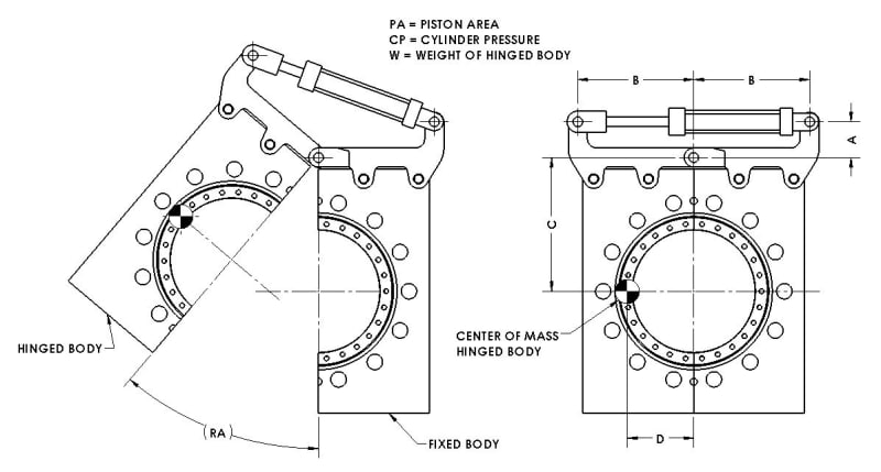
In the diagram below I need to determine the cylinder pressure required to move the "hinged body" from the closed position (on the right) to the open position (on the left).

Any help would be greatly appreciated.

Hinge_vd8ucp.jpg
 
Replies continue below

Recommended for you

Richard,

You are showing us letters, not actual numbers. You are not showing us the orientation of that thing, the mass of the part being rotated and possibly lifted, or the coefficient of friction of the hinge. When the device is closed, is clamping force required?

Have you checked to verify that those round jaws do not interfere with whatever is being clamped?

--
JHG
 
Graph the torque vs. angle at hinge axis required to hold position. Then use this to calculate force required on piston. Torque = mass * "D".

Your torque exerted by piston force is not quite as simple, as the distance from center changes as the device opens. Looks like the dimensions necessary to calculate perpendicular distance to actuator are present, but requires a skosh more math than I'm willing to just give away.
 
Thanks for the reply.
The part "Fixed Body" is fixed as shown with the ground at the bottom of the image.
The "Hinged Body" is lifted into the open position. I'm only interested in lifting the "Hinged Body" into the open position. Once the pressure is released from the cylinder gravity will cause it close on it's own.
The hinge/cylinder are only required to lift the part to the open position and do not apply a clamping force. The clamping force is achieved by other means.
I can supply some actual numbers but was hoping to come up with a formula I can use for various configurations.

I hope that makes sense.
Thanks again.
 
The "cylinder" is the same as the "piston", right?
Then the cylinder pressure would have be... negative (vacuum) in order to counter gravity, right?

Label the angle between the fixed body and hinged body as angle alpha (maybe that's what you're calling "RA").

Evaluate in static equilibrium. The sum of the two moments applied to that hinged body about the hinge is zero.

Torque due to weight = Torque due to piston (equal and opposite)
which can be rewritten as
F_Weight * Rw * cos(ThetaW) = F_Piston * Rp * cos(ThetaP)
where
F_weight = M*g
F_piston = CP * PA where again I'm assuming PA is a negative value.
Rw and Rt are the respective distances from the hinge to point of application of the force on the force on the hinged piece. That point is COG for F_w and the end of the piston for F_p
ThetaW and ThetaP are respective angles between the line of action of associated force (F_w down and F_p along the piston) and the direction perpendicular to the line between the hinge and the point of application of the force.
Of course some geometry/trig will be required to find Rw, Rp, ThetaW, ThetaP. All of these will be solved as a function of unknown/variable alpha. After you obtain a final expression, it will be in terms of alpha and suitable for graphing the answer vs alpha

Someone else mentioned friction. I neglected it here, but may need to be considered.


=====================================
(2B)+(2B)' ?
 
Two other things to bear in mind:

Avoiding ElectricPete's negative pressure, if you're pumping oil in to lift your hinged body, it will have to go in at the annulus end of the cylinder. If you have a double-acting cylinder, that's fine - but remember that the effective piston area will only be about half what's available at the full bore end.

Pressure is seldom the thing that matters in jobs like this. You control motion by getting the flow rate right - the pressure in the cylinder will be whatever it needs to be. Before you can turn that into a pressure seen at the pump, you need to understand what is going on in the valve package (if any) between pump and cylinder (some arrangements generate quite a lot of additional back-pressure as the price you pay for fine linear control of the flowrate).

A.
 
Thanks again for all the replies. I'll try to answer several points brought up all at once.

The cylinder is a double acting cylinder. The clamp is opened by applying pressure to the rod side, so yes the piston area is reduced by the area of the rod.
When the clamp is fully opened (as shown) the cylinder is fully retracted.
I'm not really concerned with flow rate or motion control.
The only requirement is to hold the "Hinged Body" in the full open position.

As soon as I get a few minutes free I'll look into the comments from electricpete a little closer and see if I can decipher those and the fish scale comment. :)

Thanks again.


A fish-scale is used to find out how much a fish weighs. It is also the name of any spring device one uses to measure weight where there is a hook to hang the load from and the user pulls or holds onto the housing. It would be used by going to the clamp and measuring the load directly,including friction in the bearings and any other forces due to interferences that will not be seen in a diagram.
 
Hi Richard A

Take moments about the hinged position so for the view on the right or closed position :- cylider force multiplied by distance A , should equal the moment due due to the mass of the moving portion multiplied by the distance D

“Do not worry about your problems with mathematics, I assure you mine are far greater.” Albert Einstein
 
Richard A:
Try this on for size, and engineering and drafting acumen. You have a good scale drawing, enlarge or shrink this so that an engineering or arch. scale will work on your new drawing. As Desertfox suggests, you want to take moments about the hinge pin center point and compare the closing moment and the opening/lifting moment. In you closed view (right view) the closing moment is (W, hinge half wt.)(D, closing lever arm, always perpendicular to the wt. vector and a vert. line through the hinge pin center) and you must overcome this with your opening moment which is (cylinder force, F)(A, opening/lifting lever arm, always perpendicular to the cylinder center line), that is (W)(D) < or = (F)(A). I don’t want to give you some dumb-assed, seven page long formula full of letters and subscripted groups of letters, I want you to kinda understand and think through the problem/process. And of course, this leads to F > or = (W)(D)/(A), and if you know F, then (PA)(CP) = F gives you the min. pressure needed to start to lift the hinged part in your right view. But, this is a moving mass, a kinematics problem, so we have some more work to do.

In your right view, draw two arcs, one through the C.G. of the hinged part, and one through the left pin center on the cylinder rod, both with their center at the center of the hinge pin, draw these arcs upward and counter clockwise. These are the paths of the rigid body motion of these two points as the hinged part moves up. The hinged part’s wt. always acts downward and its lever arm is perpendicular to this vert. vector and a vert. line through the hinge center, and you can scale (or calculate) this lever arm off your new drawing, as you wish, or are able. The cylinder force always acts on a line btwn. the two pin centers on the cylinder and the lifting lever arm must be measured perpendicular to this force vector line and to the hinge pin center. You can scale this from your new drawing or calculate it. Now, much like your left drawing shows (RA), mark off 5 or 10 degree hinging movements, from the hinge pin center, in a counter clockwise direction. These angular movement lines should cross the two arcs which show the C.G. and left cylinder pin center movements. Each of these angular increments, on each of the two arcs are the positions for the C.G. (closing moment calc.) and the lifting moment calc. (left cylinder pin center). For each angular increment tabulate the lever arm lengths, scaled or calc’ed. You know the hinged part wt., so you can calc. (F) = (W)(D)/(A) and then the min pressure (CP) to hold the hinged half. Of course, your tabulation will now show new values for F, D, A and CP as subscripted at 5, 10, 15… degrees until fully open: that is D5, D10…, A5, A10, etc.


Status
Not open for further replies.

Part and Inventory Search

Sponsor