Continue to Site

Eng-Tips is the largest engineering community on the Internet

Intelligent Work Forums for Engineering Professionals

  • Congratulations waross on being selected by the Eng-Tips community for having the most helpful posts in the forums last week. Way to Go!

Formula for warping constant of box section 3

Status
Not open for further replies.

EK1989

Structural
Jul 19, 2019
6
IE
Hi,

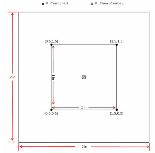
I am trying to verify the section properties that my software provides me for the warping constant but I can not find out how the warping constant is calculated. I have a box section with width and height 2 in and thickness 0.5 in. The warping constant that the software gives me is equal to 0.00730 in^6. Does anyone know if there is an explicit formula to calculate the warping constant of a box section? Although, the warping effects may be negligible in these sections, I would like to check it with some hand calculations.
WarpingConstant_fwfyja.jpg


Thank you in advance!

Kind regards,
Emmanouil
 
Replies continue below

Recommended for you

BAretired, most programs will use FEM methods from first principles to evaluate warping and torsion constants. Refer to the source code on GitHub which I linked to for the section-properties package, its all open source.
 
Thank you @FEA way for your reply and @Agent666 for forwarding the input file. I was looking on how my software calculates the warping constant and I found that it is actually calculated numerically for those type of sections. I think I will use the python code for now and any future checks instead of looking for an analytical expression.

Thank you all for your effort to answering my question!

 
Agent666 said:
BAretired, most programs will use FEM methods from first principles to evaluate warping and torsion constants. Refer to the source code on GitHub which I linked to for the section-properties package, its all open source.

Perhaps so, but I am not conversant with Python Code and was unable to find my way around in GitHub without a lot of fiddling around. Furthermore, I am not particularly interested in the formula for Cw (or Iw) at this moment. I do not approve of using software which I do not understand and, while I do not suggest the calculation is wrong, I am unable to establish that it is correct. I do not even know how to perform an approximate sanity check because I have no idea what magnitude of warping constant I should be expecting.

If the OP chooses to accept the value of Cw obtained from Python, that is up to him but in my opinion, unless he is able to satisfy himself by manual calculation, that the program is providing a correct solution, he is not justified in using the output so obtained. Unless he knows the correct expression for calculating the value for the warping constant, I cannot see how he can possibly perform the required manual calculation.

That is one of my main objections to the way software is being used by engineers today. End of rant.

BA
 
It's unlikely that you're going to find an exact formula, most formula for this sort of thing are approximations at best, best fit to the more detailed analysis results which are being disputed.

However you can verify any software by checking against known/published cases (any section tables really) for any arbitrary shapes and satisfy one's self that the underlying math involved in the derivation is correct. The programs don't care what the shape is, it's just numbers, areas, meshes etc on which the underlying principle to calculate the parameter is applied.

If you want to check by hand and get the same answer then follow the same underlying first principles method by hand. There's no simple way that I know of.

In calculating warping and torsion constants you have to resort to FEM methods for all but the most simple of cases which someone has already done the FEM approach and derived an approximate and appropriate formula.

For these formulas then how do you check them for correctness, at some point you have to accept the math is getting it right on which they were based. So while you don't have a feel for the answer, do you even need one if the underlying approach give you the same answer as 101 cases which you know the answer to?
 
Agent666, thanks for your comments. I will let it go for the time being.

BA
 
If you are interested in the fundamentals behind calculation of the warping constant and warping functions, I believe Robbies program uses this text as its basis for the computational methods.

About all I remember from university is that the warping constant is the evaluation of the following integral (I think!) ∫ω²dA, where ω is the warping function, which I cannot remember exactly what this is or how to derive it to be honest, but it got pretty complicated I remember!

So best to go to some recognised text like that linked above for further info on the theory, as I'm no expert in the underlying principles by any means.

The FEM method I reference is simply a method for numerically evaluating these fundamental integrals for a given geometry.


BAretired said:
If the OP chooses to accept the value of Cw obtained from Python, that is up to him but in my opinion,
unless he is able to satisfy himself by manual calculation, that the program is providing a correct solution,
he is not justified in using the output so obtained

I disagree. Certainly the results of computer calculations need to be verified, but I don't think it is realistic to demand
that all computer generated values be checked against "hand calculations", which often contain unknown simplifications, often
(as in this case) do not provide any insight into the mechanism being studied, and in a small but non-negligible number
of cases are just plain wrong.

In this case three totally independent software analyses have given exactly the same answer (the original calculation, the
Python section properties analysis, and Strand7). If we still want a further check we can:
- Run the analysis of the complete structure with lower and upper bound values for the warping constant, and see if it makes
a significant difference.
- If it does, or if we just want to get a better understanding of how warping works, run some computer analyses of a single
beam element, modelled initially as four plate elements, then compare that with brick elements, and look at the output
warping strains, and the reaction forces if longitudinal strains are restrained.

Doug Jenkins
Interactive Design Services
 
As an example of hand checks being incorrect/containing simplifications, all of the formulae in the AISI (and other cold formed codes) seem to be based on square cornered sections, when in reality they actually have radii at the corners, leading to a degree of error. This can make a reasonable percentage difference in the calculation of individual properties depending on the section/radii dimensions.

I recently posted this a few days ago to my personal blog exploring this concept. It was based on a recent engtips post relating to the determination of Iw for back to back channels. In that case it seemed like the manufacturers properties made some gross simplifications in deriving their properties, and I was never able to determine exactly what they did as their value neither agreed with the recognised AISI formula or the FEM result (the original poster noted they got some agreement in the post with the published value, but I didn't agree when I ran the numbers though. So it remained unclear to me what they did). In other cases I've checked manufacturers are bang on for the FEM result when compare to Python, and also using IES shapebuilder.

I guess as well, 5% difference in a section property doesn't necessarily equate to 5% difference in capacity, it could be more or less depending on the property, code, etc.

 
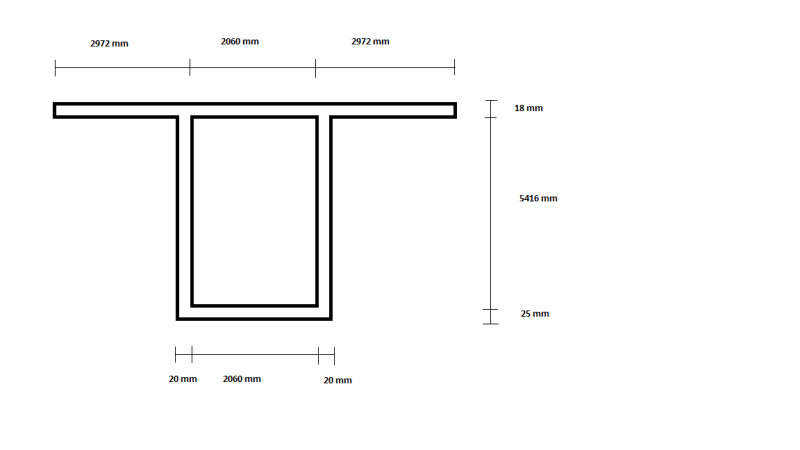
I am sorry for that but I have another issue now with the warping constant. I want to calculate the warping constant of that box section with a slab on it as shown in the attached image below. I could find how to do it with the python code. Could Agent666 provide me an input file of that combined section please? The values that I am getting from two other softwares are 1.30*10^18 and 1.47*10^18 and I do not which value is correct.

Thank you in advance!
 
 https://files.engineering.com/getfile.aspx?folder=3ba7866d-aa9c-408e-a842-18647aa87004&file=PNG_image.png
You could also try PropSection from the CTICM. It's in french but is pretty simple to use:
Link
 
In Strand7 I get 1.32*10^18.

Did you read the Python Section Properties documentation? There should be enough there to adapt the code posted by Agent 666.

Doug Jenkins
Interactive Design Services
 
Yes! I think I found it. I used an arbitrary section. I found that the 1.30*10^18 mm^6 is the correct value. That is the value that python code also provides you.

Thank you!
 
previous values were 2E6 mm^6 ?

another day in paradise, or is paradise one day closer ?
 
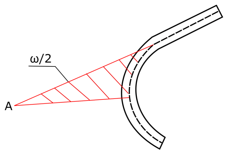
In the previous post I said that I will find the source of the formula. And I've found it. It's from the Polish book titled "Ksztaltowniki giete. Poradnik projektanta" (Cold-formed sections. Designer's Guide) by J. Brodka. This book also features a nice definition of warping function which I am going to translate and share with you since it's really hard to find good definitions regarding this topic and Agent666 mentioned that he's not sure what ω really means. So warping function is actually an area of a sector. If you take the middle line of an open section of a beam then warping function can be defined as "doubled area of a sector bounded by considered section of the arc and two radii drawn from shear center A to the points at the end of the section". I know it may sound complicated but the picture should explain it all:

warping_function_picture_wnoy1f.png
 
EK1989 said:
Yes! I think I found it. I used an arbitrary section. I found that the 1.30*10^18 mm^6 is the correct value. That is the value that python code also provides you.

The other way is to use a few 'Rectangularsections' and build it up that way and merge it together. I found sometimes with the formulation for the arbitrary section you can get a bit confused with what connects to what when you are building up the section and facets and holes with multiple regions and multiple holes if you have something quite complex.

There is a few examples of merged sections in the readthedocs documentation. Example below or merging different geometry, note you can build it up any way you like, but I chose to do an outer and inner rectangle + the 'wings'. Due to this way of doing it I needed to manually add/define the hole and an additional control point for the meshing of the rectangle which is a little counter intuitive and an after thought on my part after viewing it didn't mesh correctly in this region.

Python:
import sectionproperties.pre.sections as sections
from sectionproperties.analysis.cross_section import CrossSection

outer = sections.RectangularSection(d=5416 + 18 + 25, b=20 + 2060 + 20)
inner = sections.RectangularSection(d=5416, b=2060, shift=[20, 25])
wing1 = sections.RectangularSection(d=18, b=2952, shift=[-2952, 5416 + 25])
wing2 = sections.RectangularSection(d=18, b=2952, shift=[20 + 2060 + 20, 5416 + 25])

geometry = sections.MergedSection([outer, inner, wing1, wing2])

geometry.clean_geometry(verbose=True)
# define central hole
geometry.add_hole([1000, 1000])
# add control point for meshing hollow rectangular section correctly
geometry.add_control_point([5, 5])
# note one more mesh point to mesh resulting hollow rectangle correctly
mesh = geometry.create_mesh(mesh_sizes=[20, 20, 20, 20, 20])

section = CrossSection(geometry, mesh)
section.plot_mesh()
section.display_mesh_info()
section.calculate_geometric_properties(time_info=True)
section.calculate_plastic_properties(time_info=True)
section.calculate_warping_properties(time_info=True)
section.display_results(fmt='.3f')

 
Great! Thank you FEA Way. I am also attaching here the python's input file for computing the section properties of the previous box+slab section.

PNG_image_tylnyr.png


Python:
import sectionproperties.pre.sections as sections
from sectionproperties.analysis.cross_section import CrossSection

points=[[2952,0],[5052,0],[5052,5441],[8024,5441],[8024,5459],[0,5459],[0,5441],[2952,5441],[2972,25],[5032,25],[5032,5441],[2972,5441]]
facets=[[0,1],[1,2],[2,3],[3,4],[4,5],[5,6],[6,7],[7,0],[8,9],[9,10],[10,11],[11,8]]
holes=[[4002,2729.5]]
control_points=[[2962,12.5]]


geometry = sections.CustomSection(points, facets, holes, control_points)
geometry.clean_geometry()

mesh = geometry.create_mesh(mesh_sizes=[250.0])

section = CrossSection(geometry, mesh)
section.plot_mesh()
section.display_mesh_info()
section.calculate_geometric_properties(time_info=True)
section.calculate_plastic_properties(time_info=True)
section.calculate_warping_properties(time_info=True)
section.display_results(fmt='.3f')
 
Status
Not open for further replies.

Part and Inventory Search

Sponsor

Top