Eng-Tips is the largest engineering community on the Internet

Intelligent Work Forums for Engineering Professionals

Forward and Reverse VFD Wiring for Lift Application 6

Status
Not open for further replies.

sham96

Automotive
Apr 15, 2019
35
0
0
LK
Hello Everyone!

I have an application where I use a VFD to control a 3-Phase AC motor. The application involves a lift which is used to transfer a load from point A to B and after unloading the lift needs to return from Point B to A.
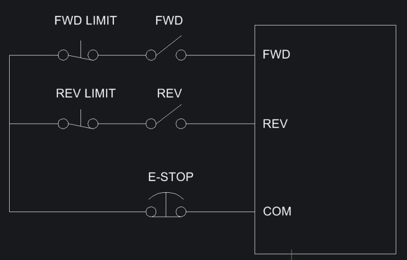
I currently am using two Normally-Open push buttons for Forward and Reverse movement and two Normally-Closed limit switches installed at point A and point B which when activated gives the STOP command to the VFD.

The twist is this:
1. After the FORWARD pushbutton is activated, the lift reaches point B and stops at the limit switch B. If the operator gives the Forward command AGAIN instead of Reverse command by mistake, then this would be disastrous since the lift will move forward beyond the limit switch and the lift cable will break.

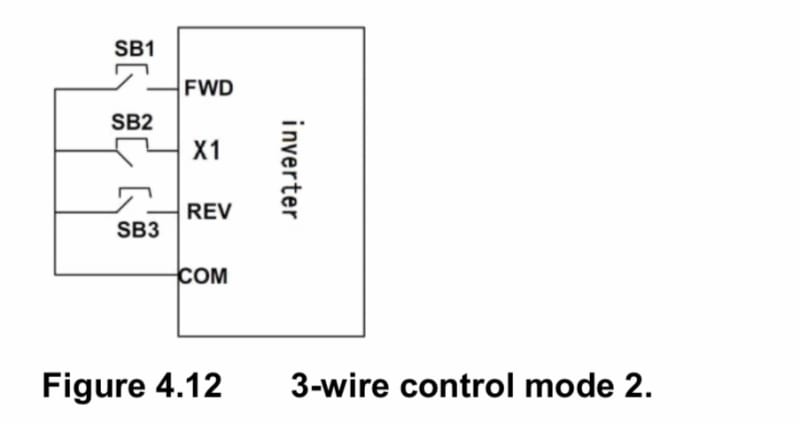
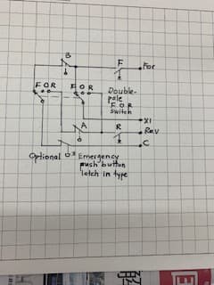
Can anyone please suggest me a wiring method I can use to eliminate the above from happening? I hope I made myself clear with the above explanation. Please feel free to ask anything! Any help is greatly appreciated! I have also attached the simplified wiring diagram that I am currently using (SB2 refers to Normally Closed Limit Switch).

38D6C071-8E19-4F57-A193-624B1E19F71F_s9mg9o.jpg
 
Replies continue below

Recommended for you

The limit switch must not only signal a stop it must disable the start signal for continuing in that direction. This can be done by using a double pole switch that has both functions, or with the appropriate use of a relay.

Also consider the possibility that the lift may coast past the limit switch before coming to a stop. Also what state are the controls in upon power-up.
 
Also what state are the controls in upon power-up.
That gets back to the "Three states of Binary" that I used to teach.
"Three states of Binary" sure got everyone's attention and made it easier to make the point that on power up, memory devices would be in a random state unless and until you added circuitry to set them to where you expected them to be upon power up.
I also used the three states of a coin:
Heads, tails and in your pocket.
When you pull a coin out of your pocket and slap it down, it may be either heads or tails.
Power up of digital circuits is similar.


Bill
--------------------
"Why not the best?"
Jimmy Carter
 
As I think everyone else is saying. You simply include a NC switch in each of the two circuits relating to the correct direction. They then stay closed until the limits in their respective directions are reached stopping further motion in that direction.

Then you include an E-STOP button in the middle direction to stop ALL motion when something is going haywire.

FWD_REV_VFD_pglget.jpg


That's a latching E-STOP press-and-it-stays until you either twist it or pull it back out.


Keith Cress
kcress -
 
Not to forget there must be mechanical interlock between the forward/reverse push buttons and electrical (and preferably mechanical) interlocks in forward/reverse contactors so that only one direction can be energized at a time.

Muthu
 
One possible issue, the OP is using momentary inputs for forward, reverse and stop functions.
I place of mechanical interlocks, cross wired NO/NC push buttons is a good second choice.
The OP is using a VFD, not reversing contactors so adding a mechanical interlock may be challenging.
If you want to use momentary contacts for forward and reverse, you may have to add some relays, and reprogram your VFD for maintained inputs.
Including the make and model of the VFD may be a good idea.
Then someone can RTFI for you.

Bill
--------------------
"Why not the best?"
Jimmy Carter
 
Dear Mr. Sham96,
Q. " ... The twist is this:
1. After the FORWARD pushbutton is activated, the lift reaches point B and stops at the limit switch B. If the operator gives the Forward command AGAIN instead of Reverse command by mistake, then this would be disastrous since the lift will move forward beyond the limit switch and the lift cable will break..."
A1. 1. I was unable to figure out a simple way to solve the problem.
2. I suggest to add a [double-pole For Off Rev selector switch]* and an (optional) Emergency (latch type) push button. The selector switch* may be For Rev without Off. See attachment.
A2. Operation:
a)when the load is at Point A, the limit switch B is close. With selector switch on F position; push push button F ; the load moves from A to B. It stops when the limit switch B is activated [from close to open]. The load stopped travelling. Any further pushing the F push button does [NOT] cause the load to move]. No damage to the lift cable ,
b) when the load is at Point B, move the selector switch to R position. Push push button R; the load moves from B to A. It stops at A, when limit switch is activated (from close to open}. Any further pushing push button R does NOT move the load nor damage to the cable,
c) for safety reasons, an additional Emergency (latch in type) push button may be as an optional. Please check the local Electrical Rules and Regulation.
Che Kuan Yau (Singapore)


IMG_7780_ujvaai.jpg
 
Thanks so much for the feedback everyone, There’s a few questions to be answered so i will get to that first!
According to the wiring I had done, the Normally-Closed limit switches at point A and B only serve the sole purpose of stopping the Lift movement (deactivate ALL signals) regardless of whether the Lift was moving in the Forward or Reverse direction. So if the Lift does stop at point B for example, all signals(FWD,REV) will be deactivated and if OP gives the FWD command again, the Lift will start once again to move in the same direction, hence my problem.
I am also using an AC Brake motor so the motor brakes immediately when STOP CMD is activated and does not coast past the limit switch.
@itsmoked I did try your wiring scheme today but I realized that with this setup, I cannot use momentary NO push-buttons. Everything else is perfect!
@Mr.Che Your wiring diagram ticks all boxes I should say and it will be the first thing we will start to work on tomorrow. Thank you so much for your diagram and your explanation, we were thinking of purchasing a PLC to control this Lift and your diagram quite possibly eliminated a huge cost for our company!
Everyone else who shared their valuable feedback, thanks a ton! Means alot [2thumbsup]
 
If the limit switch stops all motion, how does the operator cause it to move in either direction? You need an electrically operated, mechanically latched relay operated by the limit switches. Reach the limit switch at the end of “forward” and the latching relay changes state to allow only “reverse”; when that limit switch is reach the latching relay goes to forward only.
 
We need the model of the VFD so we can check what options are available for programming and control.

Bill
--------------------
"Why not the best?"
Jimmy Carter
 
Dear Mr. sham96
Please do update us whether my proposed circuitry (works or failed) after [actual field trial]. Please report on any operational defects, problems and any safety issues or any additional requirements/improvements that come to light. I will try to revise the circuitry to suit upon receipt of your [field observations]. At your service at all time, Sir.
Che Kuan Yau (Singapore)
 
Also might want to think about some sensing device where if the lift chain/cable broke, that you would set an emergency lift brake.
I have seen where either a prox was used in conjunction with a wooden wheel, where bolts are screwed into the wheel around the circumference. If you do not see the prox change state then set brake if VFD is running. I think the brake would be set if VFD is off/not running anyway. I am not a fan of that wooden wheel, due to the bolt head is not usually at same depth around circumference of wheel. So you get intermittent failures that are ghosts in machine. Sad when you see a lift table drop because of chain break and it does not stop by brake engagement.

I would use an encoder for above circumstance. Use a Pulse indicator type encoder.

I think some people are pointing out how do you get the lift off the limit switch. I have seen where you have maintenance lift switch on/off with up/down function inside the control panel. This would be a jog input on the VFD. That way only maintenance can only get the lift off these problem areas.

I am sure there are more device functions like if you have overhang on the lift. What do you do? Stop lift? This would be another function where the maint jog would come into play.
 
@davidbeach: Each VFD provides several different control modes that enable us to control its operation via its external terminals, For e.g 2-Wire, 3-Wire Control.
I have used 3-Wire Control mode where signals such as FORWARD Run, REVERSE Run are given through momentary NO push buttons and STOP via momentary NC pushbutton(Limit Switch in this case). When the limit switch stops all motion(deactivates ALL signals), the OP merely has to give the FWD or REV command to the VFD again for it to command the motor and the VFD executes the commands accordingly.
 
@Mr.Che : Sorry for my delay in updating(We had to get down the Emergency Latching/DPDT switches)but we were finally able to test your circuity and it worked beautifully and exactly according to our requirements! The lift does not move beyond the limit switches at A and B even when the OP repeatedly gives the same command and this is exactly what we wanted, to prevent damage to the lift cable. Thanks from everyone at our Company, we truly appreciate your help Mr.Che! [smile]


Dear Mr.sham96
1. Thank you for your prompt feed-back that the circuitry works to your requirement.
2. I noticed that there are other valid proposals/concerns mainly on additional "mechanical" safety devices.
3. I can think of an additional "electrical" safety precaution by (adding) an [under-voltage] release on the incoming breaker MCCB*; controlled by the N.C. contact of the same emergency (latch-in) switch**. When the emergency switch** is pushed, it switches off the MCCB* [under voltage release] , which trips the breaker.
4. Attention: The incoming breaker* shall be installed at the [up-stream/input] of the VFD . There shall be NO [ breaking devices (MCCB/contactor)] between the [output of the VFD and the motor].
5. Inform me if deem useful. I will furnish the proposed circuitry. I am at your service at all times, Sir.
Che Kuan Yau (Singapore)
 
Status
Not open for further replies.
Back
Top