Eng-Tips is the largest engineering community on the Internet

Intelligent Work Forums for Engineering Professionals

Fraction in Decimals within drawing. 7

Status
Not open for further replies.

Rayleigh

New member
Dec 20, 2022
12
0
0
MY
I'm pretty sure that this topic has been discussed again and again within this forum, but I've been through several related threads (probably 10+) and still haven't found the answer to my question. Short of browsing through all of the threads in this forum, I have decided to start one and ask here.

I come from a metric background. Designing in US customary inch fractions, while dimensioning in decimals is making me wonder about certain things.

If say, I have a part that is 0.5" and I would like a tolerance of +/-0.01", it is not an issue. I can just label 0.50" +/-0.01". During inspection of the part, QA will just have to check up to the 3rd decimal if 1/10th rule of thumb is used for measurement tool accuracy.

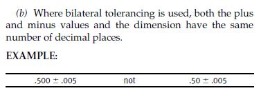
If I have a part that is 0.3125" and I would like to maintain the tolerance of +/-0.01", it is also not an issue within the drawing. I can just label 0.3125" +/-0.0100". Trailing zeroes on the tolerance as per ASME Y14.5 2009 2.3.2(b) - Bilateral Tolerancing.
3_v1ctes.jpg


However, when it comes to inspection of the part:
1. Will the 1/10th rule of thumb apply to the total value of the tolerance (i.e. 10% of 0.02" = 0.002"); meaning that the measurement system only needs to be accurate up to the third decimal, or
2. Would the trailing zeroes/number of decimals be overriding it (i.e. the measurement system will have to be able to measure up to the fifth decimal)?

Worse if I have a dimension which is from the 32th fraction, for example, 1.40625". Following ASME Y14.5 rules, I suppose the tolerance would be written as +/-0.01000". What about the inspection then? Six-decimal accuracy on the measuring system?

Drawing-wise, I can just label it as per the actual 3D dimension and the ASME rules just to be true to the part and the rules. However, I would think that this will have huge implication on manufacturing and inspection cost.

I'm sure that many of the forumers would have encountered this in real life. I would appreciate to hear on how this is case is being handled.

------------------------------------
Also on another related topic:

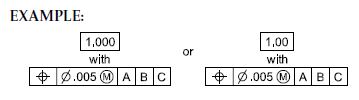
With regards to the snapshot below, would it also be acceptable for the other way around? I suppose the implication would be similar to my question above.
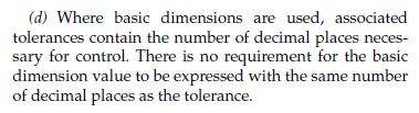
1. Basic Dimension: 1.625"
2. Positional Tolerance: Diameter 0.02" (no trailing zeroes to match the Basic Dimension)
1_qqv1da.jpg

2_c3h00w.jpg
 
Replies continue below

Recommended for you

The 10% rule applies to the range of variation, not the apparent precision.

Even then it is a stupid rule as it should be applied to the desired exclusion at the limits of the range.

Note that as the range gets smaller the available exclusion range also gets smaller, but if one wants to allow some epsilon of exclusion at the edge of the variation range, then it doesn't matter if that is a large range or a small one.

Suppose one has a range of 1 inch, but there is a part that has a variation that is 0.999999 inches and you want to accept it. To reliably accept it one needs to be far more precise, with an epsilon of only 0.000001 to work with in order to not accept anything that is over the acceptable range.

The cutoff from the design side should not affect in any way the cut off epsilon from the inspection side. That epsilon represents some amount of parts that are rejected that still meet the design requirement and that decision is an economic one.
 
So there is never a question, and no errors, show the tolerance dec places the dim same as the dim dec places.
Add a tol block, including fraction, to cover all other dim's.

Chris, CSWP
SolidWorks
ctophers home
 
1.40625+/-.01000 means the same as:

1.41625
1.39625

According to the 10% rule of thumb for measurement system accuracy, the accuracy would need to be up to the third decimal.
Measurements could be:

1.416 - pass
1.417 - fail
1.396 - fail
1.397 - pass
 
If the error in the measurement can be 0.001 then a reading of 1.41525 could represent a part that is actually 1.41625, so any value over 1.41525 should be rejected. If the reading is only to 3 places then the upper limit can only be 1.415; anything larger would fail.
 
Yes, mine is a strict approach. As opposed to accepting failed parts. Accepting failed parts causes nightmare results. QC says they pass; customer installs and they don't fit or don't work.
 
Burunduk said:
According to the 10% rule of thumb for measurement system accuracy, the accuracy would need to be up to the third decimal.

This confuses me. Is your thinking simply because the tolerance of +/- .01000 coincidentally has three zeros after that .01?
What if it were 1.40625+/-.01111? Would we still say the measurement accuracy only goes to the 3rd decimal? I presume not, so why do zeros get shortchanged?
I know that the extra zeros are there to match the number of digits in the dimension, but there seems to be no way to communicate if we want the extra zeros there as a solid part of the tolerance range, having the 10% idea applied after that.
 
Dimension and tolerance values are to be treated as if suffixed with an infinite number of zeros. The decimal inch rule appears to be solely to re-emphasize the use of decimal inch rather than metric dimensions, something that is either already identified on the drawing or in a CAD model.

At some point it boils down to an economic choice as to how closely to the tolerance limits one expects QC to validate.
 
3DDave,
If a deviation from the tolerance by the order of magnitude of the measurement uncertainty will definitely cause the part to malfunction, then the strict approach is indeed required. In many cases, such a deviation still means that the product produced is still functional, and even competitive, and in such cases, a quality policy that does not favor excessive rejection is appropriate.
 
Is it generally acceptable for QA/QC to override the engineering design team's understanding of the drawing tolerances?

Is a note "WE REALLY MEAN THIS" required for any tolerance that cannot ever be exceeded and where is that provided for in Y14.5?

How often should a product be run at the ragged edge of the tolerance zone? This is counter to every modern theory of production control.

Do you inform customers that what is on inspection reports is probably inaccurate?
 
3DDave,
Have you never participated in an MRB meeting where small deviations out of tolerance were approved?

Production control theories are great and useful, but - nothing is produced near tolerance limits?
What about small (but expensive) batches?

If the deviation out of tolerance is small enough to result from the measurement uncertainty, and considering that the measurement uncertainty is small enough for the measurement to be one order of magnitude more accurate than the tolerance, how often that results in non-functional parts?

Most often, the tolerance limits are not hard limits betweeen parts that function and those that completely not.
 
Burunduk, here's why I said not. If the drawing states 1.40625+/-.01111 then the designer wants that to be measured to at least the 5th decimal place (then 10% more or whatever).

But if the drawing states 1.40625+/-.01000 then we only measure to at least the 2nd decimal place (well, 3rd place based on the 10% rule).

Those two examples use the same number of decimal places, but the measurement accuracies will be arbitrarily different.
Tell me if my thinking is wrong on these, and then I can reformulate my question.
 
Garland,
I'm not saying you're wrong, but let me ask you this:
If the designer gives as much as 0.02222" (+/-.01111) tolerance to a particular dimension, which is actually more tolerance than 0.02000" (+/-.010000), why would he care about the impact of the fifth decimal of the measurent (which is about 0.1% of the variation he's OK with), and why wouldn't he care about it in the case of the smaller tolerance?
 
From my experience at different companies, inspectors and machinists have never heard of the % rule of thumb. Especially where I work now.
They want to know hard dimensions and tolerances.
If a dwg shows 1.40625+/-.01111, they will measure to that tol.
I have asked them about the 10% rule for example, just received blank stares.
To reduce any confusion, I suggest make it simple for them.

Chris, CSWP
SolidWorks
ctophers home
 
That's MRB, not a policy. You are saying to make it a policy of not reviewing the out-of-tolerance condition, but just accept items that are only a little out of tolerance.

What has happened in my past is that to be accepted at MRB, the related tolerance stack is re-analyzed among all the related parts and all prior inspection reports to see which have been sufficiently in-tolerance to allow the one out-of-tolerance item to function. If that is the case, the drawings are changed to shift tolerances so that all accepted variations are in tolerance.

On government contracts, which I mainly worked on, shipping discrepant material is a fast way to get barred from further work; do it enough and there can be fines and prison time. Make it a secret policy and that prison time threat moves from fraud to conspiracy to commit fraud.

As long as all the parts ever delivered are acceptable for the drawings delivered to the government and the government was informed of the MRB action, it's all OK.

I never liked this policy as it was a lot of engineering effort expended to make up for a poor performing supplier that depended on the good suppliers keeping inside their tolerances; bad suppliers were getting rewarded for cheating. Program management found it necessary to meet schedule.
 
For our company/customers, the number of decimals defined in the nominal dictate the level of precision required. In the odd instance where the tolerance has more decimal places than the nominal, we just clarify intent with the customer, which typically results in a print update.
Our inspectors don't care about the 10% rule, their job is to measure against the print with the tools given to them. The 10% rule is just to ensure your tools are capable of actually discerning variation at the tolerances requested. In automotive, measurement systems are required to have NDC > 5 to meet the inspection resolution requirements.
 
I second what ctopher states; most of the European manufacturers I have worked with also demands hard dimensions and tolerances, and will measure to those tolerances. I work with older machinists from eastern Europe; I can't tell you how much I learned from those guys over the years - and it also matches the strict approach described by 3DDave.

IMO too many companies in general accept parts that are outside the tolerance limits, because the function is not impaired; therefore making it okay (and economically beneficial) to accept the part anyway as is (ISO 2768 Section A.4 does not help on the matter, but that topic has been discussed at length over the years). This sometimes leads to failed parts and nightmarish results like 3DDave says.

IMO: If the part is outside its given tolerances then the function should be impaired; if not the given tolerances are too strict anyway and the tolerances should be increased. Then again I'm kind of old school I suppose, and in an industry that allows me to (almost) only design with regards to part and product function. But that is just how I was taught.
 
Thanks for all the replies and in-depth discussion. It has been rather insightful. It is interesting to learn of the different ways that the inch decimals are being handle at different establishments.

----------
3DDave said:
If the error in the measurement can be 0.001 then a reading of 1.41525 could represent a part that is actually 1.41625, so any value over 1.41525 should be rejected. If the reading is only to 3 places then the upper limit can only be 1.415; anything larger would fail.
Do I understand your statement correctly by saying the following:
1. In the first case, the acceptable range for the part would be between 1.39725" to 1.41525".
2. In the second case, the acceptable range for the part would be between 1.397" to 1.415"

In both these case, instead of defining the precision of the measurement system, the 10% (0.001") is rather used as a buffer zone/exclusion range from the actual limits to prevent accepting edge-cases due to rounding.

-----------
Burunduk said:
1.40625+/-.01000 means the same as:

1.41625
1.39625

According to the 10% rule of thumb for measurement system accuracy, the accuracy would need to be up to the third decimal.
Measurements could be:

1.416 - pass
1.417 - fail
1.396 - fail
1.397 - pass
I do see where you're coming from. However, in the case where if a more precise measurement system was used and the 1.416" reading was actually 1.4163", for example, then this would technically still be out of tolerance. Then again, I do agree with you that the such parts could potentially still be accepted as long as necessary MRB actions and documentations have been performed.

Just being curious, is this truncation something that is actually being practiced at where you are/from your previous actual experience, or is this just your theoretical understanding?

-----------
ctopher said:
From my experience at different companies, inspectors and machinists have never heard of the % rule of thumb. Especially where I work now.
They want to know hard dimensions and tolerances.
If a dwg shows 1.40625+/-.01111, they will measure to that tol.
I have asked them about the 10% rule for example, just received blank stares.
To reduce any confusion, I suggest make it simple for them.
Since you have access to inspectors and machinist, please do not mind that I ask how would 1.40625+/-0.01 be handled by your inspectors and machinist?
1. Would the inspectors determine that a vernier caliper is sufficient to verify the dimensions of the part or would they use something that is more precise that can measure up to the 5th/6th decimal?
2. I suppose, for a machinist, the tolerance band would be the one dictating the machining hours required, machine capability and subsequently cost, rather than the number of decimals. Haven't myself worked directly with a machine, I am assuming that keying in 5 decimals into their programming is just as easy as writing down 5 decimals on my drawing.

-----------
Mech1595 said:
For our company/customers, the number of decimals defined in the nominal dictate the level of precision required. In the odd instance where the tolerance has more decimal places than the nominal, we just clarify intent with the customer, which typically results in a print update.
So in this case (1.40625 +/-0.01), where the number of decimals defined in the nominal is more than the number of decimals defined in the tolerance, how would your company/customer dictate the level of precision required?

-----------
Looking forward to read all of your answers.
 
Status
Not open for further replies.
Back
Top