Eng-Tips is the largest engineering community on the Internet

Intelligent Work Forums for Engineering Professionals

Fraction in Decimals within drawing. 7

Status
Not open for further replies.

Rayleigh

New member
Dec 20, 2022
12
0
0
MY
I'm pretty sure that this topic has been discussed again and again within this forum, but I've been through several related threads (probably 10+) and still haven't found the answer to my question. Short of browsing through all of the threads in this forum, I have decided to start one and ask here.

I come from a metric background. Designing in US customary inch fractions, while dimensioning in decimals is making me wonder about certain things.

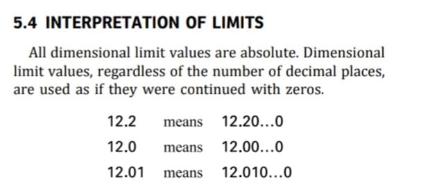
If say, I have a part that is 0.5" and I would like a tolerance of +/-0.01", it is not an issue. I can just label 0.50" +/-0.01". During inspection of the part, QA will just have to check up to the 3rd decimal if 1/10th rule of thumb is used for measurement tool accuracy.

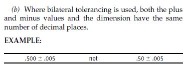
If I have a part that is 0.3125" and I would like to maintain the tolerance of +/-0.01", it is also not an issue within the drawing. I can just label 0.3125" +/-0.0100". Trailing zeroes on the tolerance as per ASME Y14.5 2009 2.3.2(b) - Bilateral Tolerancing.
3_v1ctes.jpg


However, when it comes to inspection of the part:
1. Will the 1/10th rule of thumb apply to the total value of the tolerance (i.e. 10% of 0.02" = 0.002"); meaning that the measurement system only needs to be accurate up to the third decimal, or
2. Would the trailing zeroes/number of decimals be overriding it (i.e. the measurement system will have to be able to measure up to the fifth decimal)?

Worse if I have a dimension which is from the 32th fraction, for example, 1.40625". Following ASME Y14.5 rules, I suppose the tolerance would be written as +/-0.01000". What about the inspection then? Six-decimal accuracy on the measuring system?

Drawing-wise, I can just label it as per the actual 3D dimension and the ASME rules just to be true to the part and the rules. However, I would think that this will have huge implication on manufacturing and inspection cost.

I'm sure that many of the forumers would have encountered this in real life. I would appreciate to hear on how this is case is being handled.

------------------------------------
Also on another related topic:

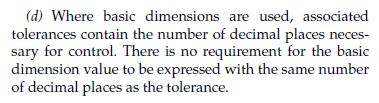
With regards to the snapshot below, would it also be acceptable for the other way around? I suppose the implication would be similar to my question above.
1. Basic Dimension: 1.625"
2. Positional Tolerance: Diameter 0.02" (no trailing zeroes to match the Basic Dimension)
1_qqv1da.jpg

2_c3h00w.jpg
 
Replies continue below

Recommended for you

ctopher, I agree with you on the limits of the acceptable dimensions. No arguments there.

However, what I am trying to understand is more towards how they would measure it/what would they use to measure it.

In this case where the limits have five decimals, would they:
1. Just measure with a vernier caliper as long as the dimensions are within say, 1.397" and 1.415"
2. Move on to a more precise measurement tool if the measurement were to fall on 1.396" and 1.416" to verify that they are still within the tolerance range
3. Or don't bother and just reject parts with dimensions 1.396" and 1.416"
4. Or just slap everything on the most expensive measuring machine in possession?
5. Something else.

I have the understanding that requiring higher precision of measurement would translate to a higher manufacturing cost. Therefore, as the designer and drafter, I would like to understand if dimensioning in a certain way would impact the manufacturing and inspection cost of the part. If by labeling the dimension as 1.40625 +/-0.01 will increase the cost by 10x just because the manufacturer will now require a machining/measurement tool that is capable of measuring up to the 5th/6th decimals, when the part only actually require a precision of up to two decimals, then at least I could be more aware of it and can perform corrective action such as adjusting the design so that it can still work with 1.40 +/-0.01 or 1.41 +/-0.01.

However, if there are some approaches that is being put into practice to limit the required precision of the measurement tool based on the tightness of the tolerance range, rather than the number of decimals, or some other rules, I would like to know about it too.
 
It really depends on the feature and their best method of measuring that feature. They have everything from calipers, to CMM, to 3D scanner.
Engineering doesn't dictate to them which tool to use. They are the inspectors, they tell us if it falls within the tolerance.

Chris, CSWP
SolidWorks
ctophers home
 
"2. I suppose, for a machinist, the tolerance band would be the one dictating the machining hours required, machine capability and subsequently cost, rather than the number of decimals. Haven't myself worked directly with a machine, I am assuming that keying in 5 decimals into their programming is just as easy as writing down 5 decimals on my drawing." - No. Far from it actually. If you write down the decimal, you have defined the tolerance to that decimal. If it's on the drawing you have to inspect it. And with that many decimals you might have to take into account thermal expansion during the machining process, warping of the material itself, thermal stress relief of the raw material and most likely post-machining as well, any surface treatment will have to be taken into account on top of that. Not to mention the machine you to produce the part; are you using the correct tool? Tool-holder? If not vibration might be enough to cause you fail inspection. Half-dovetail grooves is a good example, where the top-rad often is 0.005''. If the cutter is slightly chipped you will be out of the acceptable tolerance area, and clipping of the O-ring might occur; product function is not intact.

Vernier callipers might work if the geometry allows the use of it for sure. They generally offer accuracy up to 0.02 mm (0.0001''). For higher accuracy you would use micrometers. For deep holes you can use calibrated gauges; or use something like an EMCC D-5SB with a resolution of 0.001 mm with an accuracy of 0.002 mm. There are many tools, and the cost increases with stricter tolerances.

To your last question: in that case I would confer with the customer on the importance of the tolerance. I have many times ended up with buying specialized gauges due to strict tolerances; it is not uncommon. On the other hand I also have customers who says: "oh... good point. That dimension is not really that important, +- 0.5 mm is fine...".
 
Prometheus21

When I mentioned keying in 5 decimals into the machine, I was referring to the nominal dimension, not the tolerance (Or are you telling me that the machine doesn't see the difference?). I do understand that dictating a tolerance of +/-0.00001" on a drawing will cost me a lot more in both manufacturing and inspection cost than if it would had been if I had requested for +/-0.01" only instead.

My personal internal debate is more towards resolution of nominal dimension vs resolution of tolerance. Let us loosen the tolerance even further just to be make my question clearer. So in the case of 1.40625" (1 13/32 inch) +/-0.1", the tolerance band is rather laxed but the nominal dimensions is listed out to the fifth decimal to stay true to the fraction. Let us also say that this dimension is the size of a cube just to eliminate any other variables.

1. Since the tolerance band is somewhat widen, would all of the issues (thermal expansion, warping, etc.) previously listed for the machinist go away/be less of an issue. Or will they still be present since the the machining process is still dictated by the resolution of the nominal dimension no matter the laxness of the tolerance band?
2. Will the inspectors see the wide tolerance band and decide that all that expensive machinery is not necessary or would they still have to use them any way due to the presence of the fifth decimal in the nominal dimension?

So if I were to send this cube to a third party manufacturer, will they just look at the five decimals in 1.40625" and give me an expensive price tag despite the tolerance being +/-0.1". Or will they go, "With that wide of a tolerance, my machine has no problem making and verifying it quickly" and provide me with a reasonable price tag?

Perhaps all of my issues would not have existed if I had ignored the fractional side of the US customary units and just use decimal inch from the get go. [upsidedown]
 
To your last question the answer is: Yes.

Tossing drawings to production and 3rd party inspection is asking for trouble. This discussion should be between your own QA group and the supplier QA group. Expect them to ask for your input.
 
Rayleigh,
I think you may be overthinking it.
My suggestion is make some preliminary drawings, same part tolerance both ways, get some quotes.
I'm curious the outcome.
My guess, if you dim 1.40625 +/-0.1, they may either question it, or misread it and assume you are looking for a looser tol.
If you dim 1.40625 +/-0.00001, they may no quote because they can't do it, or have a higher $$ because it's too tight.
They may also ask for a STEP file, which should be at nominal.


Chris, CSWP
SolidWorks
ctophers home
 
"Or are you telling me that the machine doesn't see the difference" - It depends on the machine. Most of them does differentiate between nominal and actual tolerances(Not older models, you would be surprised how many manufacturers uses equipment from the 40's, 50's and 60's still in some part of their production). Now if you actually get what is typed into the machine is a whole other matter. We had an Ø16 f7 tolerance that kept being out of specs recently, but only in the early mornings. Turns out the heating wasn't set to on for a few hours at night, which affected the ambient temperature around the machine sufficiently enough so that the calibration in the machine got affected. The machine had to "get warmed up" before reaching the desired values typed into the machine; this was an older Mazak Machine(> 10 years old).

I understand your problem better now. I have had similar problems when designing equipment meant for US customers, as they want the drawing in imperial units, not metric units. My experience is that the customer will have to specify their own needs in writing in case of any ambiguity regarding unit conversions:

So to take your cube to continue this example: if the cube is 1 (13/32 inch) +/-0.1", this is in metric units: 35.7188 +- 2,54 mm. Our workshop would to make it easier and tighten the tolerances slightly into simpler but stricter metric units: e.g. 35.7 +- 2.4 mm. This solution is possible for some customers (and for some tolerances), and they are happy with this solution. Note that we would send the original drawing with the new tolerances marked in red, and get approval from the customer to make these changes. This is often done (and accepted) when producing filling equipment for valves described in CGA V-1.

Some customer does NOT accept this: in those cases we use the full tolerance band (35.7188 +- 2,54 mm) and measure to the final decimal if needed. Note that we would discuss the specific need for this with the customer. If the customer demands a type 3.1 or 3.2 inspection certificate this is often the case. The cost increases due to the need for stricter inspection protocols.

Another option that I have done is to look at the product function with the customer and agree to round up or down the imperial units to the nearest metric unit with either 1,2 or 3 decimal accuracy.
We had a customer who used Ø 11/16'' (17,46 mm) bar specification on their drawing. After talking to the customer we agreed to use Ø 17.50 for the production of the part.

"1. Since the tolerance band is somewhat widen, would all of the issues (thermal expansion, warping, etc.) previously listed for the machinist go away/be less of an issue. Or will they still be present since the the machining process is still dictated by the resolution of the nominal dimension no matter the laxness of the tolerance band" - It depends on the workpiece. But a larger tolerance band will make the part easier to make. Note that the difficulty arises when you are on the higher or lower end of this band due to the need for higher measuring accuracy. The issues mentioned above will have a much larger impact if you are working at the outliers as in comparison to the middle of the tolerance band. Our eastern European machinists always create 1 inital part that is taken for inspection and approval before commencing with the main production. They will keep making this 1 part until they "get it right"; meaning the part is within specs.

"2. Will the inspectors see the wide tolerance band and decide that all that expensive machinery is not necessary or would they still have to use them any way due to the presence of the fifth decimal in the nominal dimension?" - See above. But if the cube is manufactured at 35,7 mm nominal and has a +- 2 mm deviation you are well within specs and there is no need to check the decimals. Now if the machinist produces the cube at 33.2 mm I would be worried since the lower limit is (35.7188 - 2.54 = 33.1788). The machinist would then have to use the time to check if the product really is 33.20, or 33.19, or 33.18, or 33.17 and therefore out of spec).

"So if I were to send this cube to a third party manufacturer, will they just look at the five decimals in 1.40625" and give me an expensive price tag despite the tolerance being +/-0.1". Or will they go, "With that wide of a tolerance, my machine has no problem making and verifying it quickly" and provide me with a reasonable price tag?" - Hopefully the last one;) That being said I have experienced both when we have outsourced some part of the production. Some suppliers will use ANY excuse to up their pricetag. Our company has limited the number of suppliers to a minimum for that very reason. With the remaining suppliers I can easily have a technical discussion going like this:

"Why is the pricetag so high?" Answer: "The bend radius in detail A is 24 +- 2 mm. This requires a special bending tool. The standard bending tool in-house is 24 +- 2.5 mm. If you can accept this then we can give you a new offer". We get a lower pricepoint and they get to produce the part more efficiently, allowing them to take on more work -win/win.

"Perhaps all of my issues would not have existed if I had ignored the fractional side of the US customary units and just use decimal inch from the get go." - It is (often) a pain, no doubt about it. There is a reason there have been so many accidents out there due to bad conversion between units.
 
Rayleigh and everybody,

This issue tends to be overcomplicated more than necessary.

If a dimension has a large tolerance but many decimal places, the choice of measuring tool should prioritize the tolerance rather than the number of decimal places. Inspection does not need a highly accurate and expensive tool if the tolerance is large, even if the dimension is specified with many decimal places.

Does this make sense?
 
3DDave said:
It could have been 1/3 of an inch, so there's that.

There must have been a reason that 1/3 and its sibling 2/3 were barred from joining the official fractional family of the US Customary Units. Otherwise, the amount of energy required to achieve the level precision that is true to their fractional values would have caused the world to implode into non-existence.
 
Rayleigh said:
So in this case (1.40625 +/-0.01), where the number of decimals defined in the nominal is more than the number of decimals defined in the tolerance, how would your company/customer dictate the level of precision required?

I think everyone else already gave you better info that I ever could, but I'll answer anyway since you asked.
For us, it would be the same as Ctopher mentioned, this would define the following spec range where anything outside is considered non-conforming:

LSL: 1.39625
USL: 1.41625

A measurement system would then need to be chosen that's capable of accurately measuring the difference between, for example, 1.39624 (Fail) & 1.39625 (Pass). Otherwise you technically run the risk of inadvertently shipping bad parts that measured OK, or rejecting good parts that measure NOK.
Whether or not that's feasible entirely depends on the product, process, and tools available to your company. My customers are notorious for sending in obscenely strict quality requirements for items that the process is physically incapable of maintaining. I have to remind them that this little flexible piece of plastic isn't a critical link in the life support hardware for a Mars colony, and just holds their phone in some crappy mid-level trim sedan.
 
So if we consider this Y14.5 rule:
Screenshot_20240911_164651_Drive_omrequ.jpg


Making the efforts to measure by a system that can distinguish between 1.39624 (Fail) & 1.39625 (Pass) for a dimension given as 1.40625 +/-0.01 makes no more sense than making the efforts to measure by a system that can distinguish between 1.29999 (Fail ) and 1.30000 (Pass) for a dimension given as 1.31+/-.01.
 
Burunduk,

Does this section 5.4 not support the idea that limit decimals are driven by the resolution of the nominal [edit: in this example], as the limits are defined to infinity?
What am I missing?

E.g

1.31 +/- 0.01
1.312 +/- 0.010
1.3124 +/- 0.0100
1.31241 +/- 0.01000
etc...
 
Mech1595,
You are not wrong,
But it also means that 1.31+/-.01 is the same as 1.3100+/-.0100 , as a requirement. So why use a much more accurate measurement system for the latter (or much less accurate system for the former)?
 
Let's say I have a post length that reports as a nominal of 1.31 at 2 decimals. But if I increase the decimals, the nominal becomes as follows:

1.31
1.310
1.3104
1.31042

The inclusion of more decimals results in a stricter definition of the dimension. Even if the dimension is 1.310....0, the concept is the same; 0 is still a number, and I have to validate the components to the precision dictated on the drawing.

1.31
1.310
1.3100
1.31000


As a semi-related note, I had kind of the opposite situation recently, where the customer had specified 1.5 +/- 0.02 mm on their print for a dimension.
My QA's reported the dimension as 1.50 +/- 0.02 on the layout, but were measuring on average 1.45. When I checked the CAD, the nominal was actually 1.46 at 2 decimals, which brings the parts in-spec. Had to request a print update.

 
Mech1595 said:
Let's say I have a post length that reports as a nominal of 1.31 at 2 decimals. But if I increase the decimals, the nominal becomes as follows:

1.31
1.310
1.3104
1.31042

The inclusion of more decimals results in a stricter definition of the dimension

The difference between those values would only matter if they were all borderline conditions relative to the allowable dimension range; for example if 1.31 is the upper limit. That upper limit could be expressed as 1.31, 1.310, 1.3100, or 1.31000 without any difference.

In your example once the fourth decimal is determinable the part is rejected for measuring 1.3104 (fail). But since the limits are absolute, technically the part must also be rejected if the actual value is 1.310001. Even if measuring to that accuracy was somehow practical, I don't think anyone would insist on such measurement when the requirement is 1.29+/-0.02 (which, according to Y14.5, means the same as 1.2900000000+/-0.0200000000).

Then, what should dictate the accuracy of the measurement system? I say it's the width of the tolerance band, not the number of decimal places on the drawing.
That is also why gagemakers' tolerances are 5%-10% of the related feature tolerance according to the applicable standards. Regardless of the number of decimals on the drawing.
 
Status
Not open for further replies.
Back
Top