Eng-Tips is the largest engineering community on the Internet

Intelligent Work Forums for Engineering Professionals

Free body diagram and cylinder force help 2

Status
Not open for further replies.

grunt58

Mechanical
Feb 4, 2005
490
0
0
US
This is not homework. I've taken some engineering classes so I'm familiar with the theory and terms. I've just never been good at applying it.
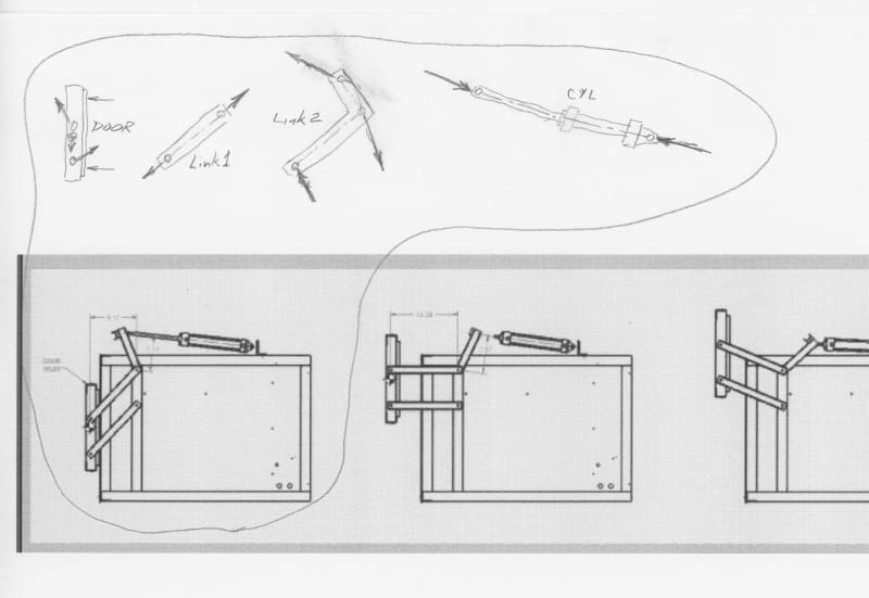
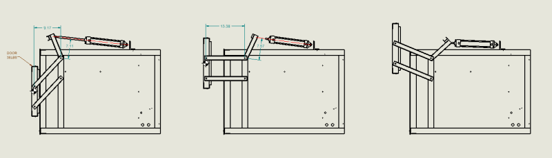
I'm building a little enclosure with a pneumatic cylinder-actuated door. Need some help making the free-body diagram and force needed to open the door. If someone wouldn't mind sketching the free body diagram and writing the formula I'd appreciate it.

Screenshot_2023-11-07_081926_u2ypub.png
 
Replies continue below

Recommended for you

Attached is what I came up with. Its been awhile now since I looked at this as I have been retired for close to 3 years now and have not not done serious mechanical design calculations even longer than that. I still not could read your dimensions very well so I just made up some hypothetical dimensions, angles and weight of door.

The way I look at it is that the moment arount the pivot point has to be always zero for static equillibrium to exists. The component of the weight of the door multiplied by the perpendicular distance to the pivot point has to be equal to the cylinder force perpendicular to the pivot point times the perpendicular length to the pivot point. Once you solve for this then everything else can be determined by trigonometry.

I don't see where the bottom arm carries any load except for minor imbalances to keep the door straight vertical. This is because any horizontal pull exerted on the upper "L" arm section by the cylinder force will be balanced by an equal force of the pivot point on the upper arm, so none of the horizontal force is transfered to the lower "L" arm connecting the door. Also all vertical loads on the "L" arm are balanced by equal but opposite loads of the pivot point on the "L" arm.

And I just did the lowest position but you can extrapolate that to the other positions.
 
 https://files.engineering.com/getfile.aspx?folder=edfea5ca-0f4d-4bf2-82e1-00e464cfbecb&file=Link_FB_Diagram.pdf
In that last diagram as the arm approaches 45 degrees the actuator force required to raise the weight will increase markedly as 45 degrees is the maximum possible.

Remember - More details = better answers
Also: If you get a response it's polite to respond to it.
 
To me the case that determines the required cylinder force is when the door is fully open. The force vector of the cylinder is way past perpendicular from the arm. A lot of the cylinder force is in the X axis.
The free body diagram at that position will tell you the perpendicular force required to keep the door open. Then you can work back to the force required by the cylinder.
 
As long as the cylinder force line of action is not through the link pivot about which the link rotates there will still be a moment about that pivot. The force will be high to create the moment necessary to hold or move the door, but still there. The limiting angle will be up to the designer considering all options.

Ted
 
Status
Not open for further replies.
Back
Top