Eng-Tips is the largest engineering community on the Internet

Intelligent Work Forums for Engineering Professionals

Free Body Diagram - Angled Bracket Support

Status
Not open for further replies.

AwesomeAndy3

Civil/Environmental
Jan 26, 2021
10
0
0
CA
Hi everyone,

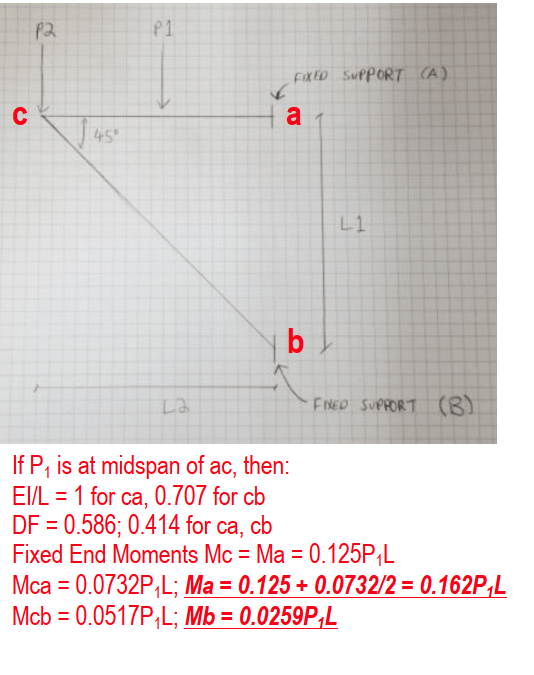
I hope this is the right place to post this question, but I'm wondering if the free body diagram below can be solved? Or would it be indeterminate?

See below for picture. The two beams are angle irons.

20210706_115658_cr741x.jpg


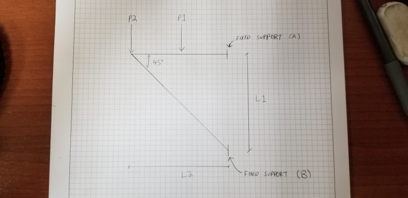
Assuming I know values for forces P1 and P2, lengths L1 and L2, is there a way to calculate the reaction forces and moments at fixed supports A and B?

Any help is greatly appreciated.

Thanks,
 
Replies continue below

Recommended for you

yes, simple statics, made more difficult because of your fixed joints.

With pinned joints is it merely ...
1) take moments about A (or B) to solve Rb (or Ra); then
2) sum forces in x-direction ... Ra is just the horizontal component of Rb.

But because you have fixed joints, the fixity moments mess with the moment equilibrium.
This means the structure is doubly redundant, which can be solved by hand (I would use the unit force method).

another day in paradise, or is paradise one day closer ?
 
Can joints be assumed to be pins? That means simple statics can be used. If P1 is in the middle of the beam, the vertical reaction at A is P1/2; at B is P2 + P1/2. The horizontal reaction at A and B is (P1/2+P2)*L2/L1, tension at A, compression at B. Since the angle is 45[sup]o[/sup], L2/L1 = 1


BA
 
The joints are both welded, thus it has to be considered as fixed supports. For doubly redundant (I assume this means second degree of indeterminant), how would you approach this problem? If I make bending Moment at A as a unit of 1, wouldn't I still have too many unknowns?
 
Just because it's welded doesn't mean it's fixed. There are lots of welded shear tab connections out there that are idealized as pins.

But assuming you are correct and the connection develops sufficient rigidity to be considered fixed, you can use the force method as rb1957 suggested. Here's a youtube video that walks through an example.
 
If joint A is really fixed, the moment at A will be, to all intents and purposes, the fixed end moment of a beam with P1 near the midspan and a roller at the outer end. You can get that from any text book. Moment at B will be near enough to negligible since there are no loads on the sloping member. So the vertical reaction at B will be equal to P2 plus the outer load of the beam with one end fixed. Pretty straightforward.

BA
 
Solving a doubly redundant system is not for the light hearted. It's not impossible, just involved. You've been given plenty of leads.

You say welded joints MUST be considered as fixed, because of the stiffness of the weld. You do realise that that is as inaccurate as assuming them to be pinned as the "truth" is somewhere between the two extremes.

Even if you are going to used the fixed joints solution, I'd suggest working out the pinned solution (it is very easy) so at least you've a benchmark for when you complete the complicated fixed solution. I would also suggest fixing one joint at a time (and leaving the other pinned). This is a single redundancy and easier (much) to calculate. This way you can see your solutions trending to the doubly fixed problem.

another day in paradise, or is paradise one day closer ?
 
To be honest, I'm approaching this problem as fixed supports because I'm checking to see if the welds will be able to hold the structure with applied load, so I would need to know the bending moments at supports A and B and compare it to the welding strength at both locations.
 
Also, just responding to BAretired, you said there are no loads on the sloping member, what if the two beams are technically separate? and the sloping member is welded to the left end of the beam, wouldn't that sloping member technically be under some load?
 
If the two members are welded together, creating a rigid joint then yes, there could be an applied moment at the junction point. Your sketch does not indicate whether the joint at the left end is pinned or rigid. I assumed a pin. If it is a rigid joint, then there would be a moment M at the junction and a carry-over moment M/2 at point B.

You also stated the members are angle irons but you do not show a connection detail. You likely have torsion on both angles as well.

BA
 
Fixed_Frame_Reactions_ib4drx.png

I'd guess that the "Q" should actually be "P" since it is the essential variable that is missing from the equation. The formula comes from this this website and there's another very similar frame (shown above) that has a very similar equation that uses "P".

If you're going to end up using one of these complicated formulas that you didn't derive, make sure you rationalize the results by comparing them to some simplified checks. (Checking the horizontal member as a propped cantilever with a midspan load should get you somewhat close for the moment reaction, and the all pinned model should get you close for the shear and axial reactions.) Also, realize that your calculated end moments will be off from the actual moment to some degree since it is indeterminate, so it would be good to have some additional available capacity.

Structural Central
 
Thanks, ProgrammingPE. I suspect you are correct about the meaning of Q. I completely agree with your cautionary message.

Another method of analysis is moment distribution, applying the fixed end moments to the beam in the OP sketch and distributing the moment at the left end. One cycle is all that is required when the supports are fixed.

Since the members are angle irons, there will likely be eccentricity at the connection. If the angles are connected back to back, there will be bi-axial bending and torsion on both members. That would be difficult to take into account, so the design should err on the conservative side.

BA
 
it seems odd to have "P" in one equation (Va, and Hb) but "Q" in the other (Ma, Mb). If one cared one could run through the math.

what is "H" (as in Hb) ?

BA brings up a good point about the apex of the frame ... is it pinned or fixed ? in the problem or in the USAF solution ?
I assume in the problem it is welded, like the ends, and so fixed.
But in the USAF equations ?


another day in paradise, or is paradise one day closer ?
 
AwesomeAndy-

Just for perspective. What are the approximate dimensions of your angle bracket and approximate loads? Are we talking 1 kip or 30 kips? Also, are the horizontal member and diagonal the same steel section with the same stiffness?

If the geometry is small and the loads are small; I would just assume it's statically determinant and move on with life.
 
Using moment distribution, and assuming P1 is at midspan of ac, Ma and Mb are shown in bold, underlined, italic print. P2 does not produce moments at A and B.

image_slv6ff.png


BA
 
"P2 does not produce moments at A and B" ... disagree. The offset moment P2*L2 is reacted by a couple between A and B and by fixity moments at A and B.

another day in paradise, or is paradise one day closer ?
 
rb1957 said:
"P2 does not produce moments at A and B" ... disagree. The offset moment P2*L2 is reacted by a couple between A and B and by fixity moments at A and B.

Well, if you want to split hairs, there is a slight moment as a result of P2 because of axial deformation in the members. If you analyzed it using a frame program, you might find a negligible moment value at A and B as a result of P2. But to all intents and purposes, the P2*L2 moment is carried by horizontal reactions at A and B. Axial deformations are not considered in a hand calculation.

Looking at Frame 9 above, Ma and Mb both have Qcd in the numerator times some bracketed expression, but for P2, d = 0, so the expression equals zero.


BA
 
Status
Not open for further replies.
Back
Top