Eng-Tips is the largest engineering community on the Internet

Intelligent Work Forums for Engineering Professionals

  • Congratulations waross on being selected by the Tek-Tips community for having the most helpful posts in the forums last week. Way to Go!

FREE BODY DIAGRAM - Moment and Force of Short Crank for Shedding Motion

Status
Not open for further replies.

marvelio

Mechanical
Feb 22, 2021
5
0
0
ID
Hi

I am currently trying to make a structural analysis of a Short Crank. It is a part of Shedding Crank in a weaving machine. I'm going to make the simulation using ANSYS and I need to know the force direction and moment of the short crank.

It will be a pleasure for me if you could help me to draw the moment and force direction, or even the equation. I will attach some images for the reference. Thank you very much.

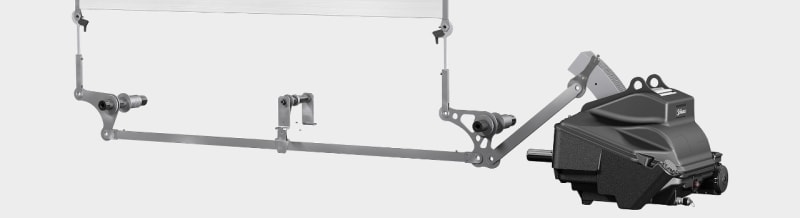
This is the plain version
Staubli_Shedding_smezys.jpg


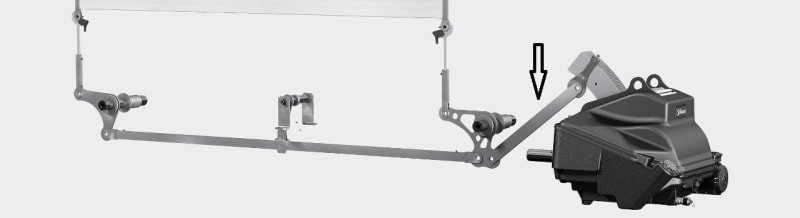
This is the part I want to analyze
Shedding_Crank_2_pukaor.jpg


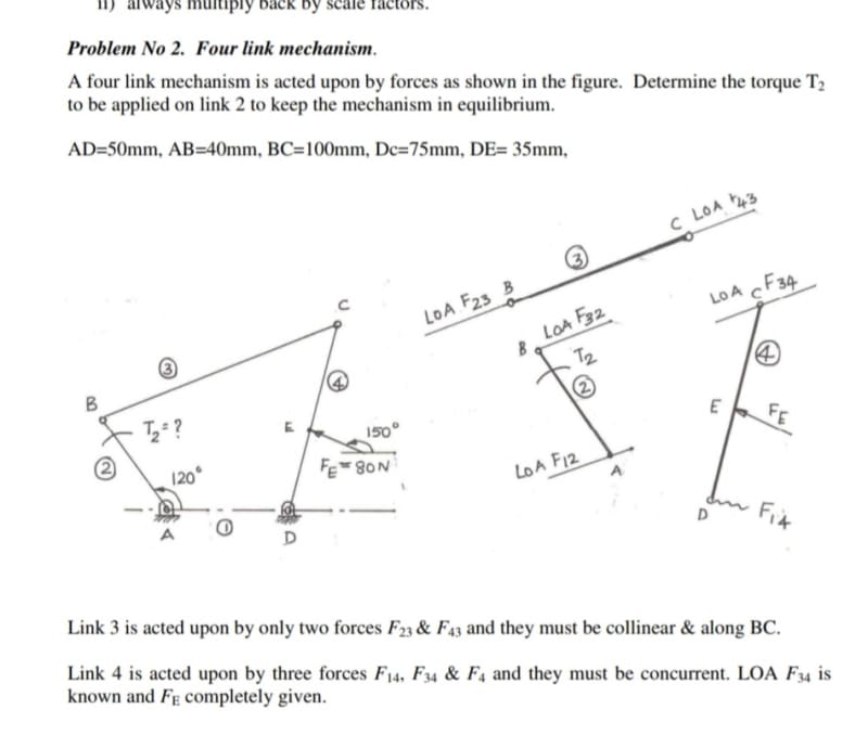
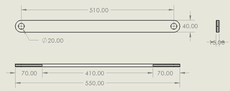
Engineering Drawing of the part
Dimensi_Short_Crank_sjadqz.png


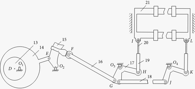
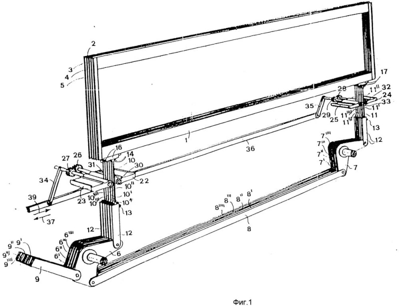
This is the full version of system illustration
Shedding_Crank_oj31mz.jpg
 
Replies continue below

Recommended for you

Hi marvelio

If you are analysing the just the component shown in the “engineering drawing of the part” then that’s straight forward because it’s what we would call a two force link, where the external forces can only be applied at the pinned ends, watch this video:-
Can give you any other information because I or we here, don’t know what speed, power or anything else about the shredder until you tell us?


“Do not worry about your problems with mathematics, I assure you mine are far greater.” Albert Einstein
 
desertfox said:
Hi marvelio

If you are analysing the just the component shown in the “engineering drawing of the part” then that’s straight forward because it’s what we would call a two force link, where the external forces can only be applied at the pinned ends, watch this video:-
Can give you any other information because I or we here, don’t know what speed, power or anything else about the shredder until you tell us?

Hi thank you for the hints before. I still don't get it how to apply the external forces since its two ends are both moving (not fix supported), pushing the long crank one. Is it possible to just use Fx and Fy to determine the forces? I need the direction of the forces and input it into ANSYS Static Structural.

Anyway, here's the additional information:
- Shedding speed: 560 rpm
- Electric motor power: 3.0 kW
- Electric motor type: 3 phase induction
- Electric motor speed: 1410 rpm
- Electric motor frequency: 50 Hz

The electric motor transmits the power through pulleys and gears so the Cam can move and the cam is connected to the short crank (the one I want to analyze). However, I don't have the precise dimensions of pulleys and gears. Is it needed to determine the moment and the force?
 
yes, different positions will have different loads. The link travels through an arc ? Constant torque (from drive) ...

But this is a simple "two force" member (axial load only).

another day in paradise, or is paradise one day closer ?
 
The direction of the forces on the link are always colinear with the centerline of the link. No moments exist at the pins. The mechanism geometry will determine the direction of the forces, the orientation of the link throughout its motion.

Ted
 
Hi, it's been nearly a month and I still don't get it how to make the equation of motions. Can anyone help me? Because I am confused with the direction of the force..
 
1) how does the lower lug move ? the "horizontal" beam is rotating about it's supports, so you "should" be able to appreciate how the lower lug of your link is going to move. If all else fails, draw a "stop motion" picture of the "horizontal" beam ... say 10degree rotations of the links.

2) how does the upper lug move ? does the arm it's attached to rotate, back and forth ?

3) since you know the starting position, you can make a "stop motion" set of pictures of the entire mechanism ...
rotate the links holding the "horizontal" beam 10degrees ...
this moves the lower lug ...
from this location draw and arc representing possible positions of the upper lug (since you know the distance between the lugs) ...
then draw and arc for the upper link, showing how it moves ...
where these arcs intersect is where the upper lug is ...
so now you know the position of the link.

Now you have to figure out the load in the link. Presumably it is driven by one of the links supporting the "horizontal" beam ?
drive torque tells you the load in the horizontal beam,
a free body diagram will tell you the load in your link,
assuming static equilibrium. Accounting for dynamics of the mechanism may be a minor change.

Or is the mechanism driven from the left hand end ? The motion of ptF is contained by rotation about O2, and the motion of ptG is rotation about O3 ?

another day in paradise, or is paradise one day closer ?
 
Hi marvelio

Yes its similar to the green beam in the link you posted so you are on the right track.
So what you should do is put that link in all the different positions for different positions of the driving crank and then workout the forces in the green link for the different crank positions

“Do not worry about your problems with mathematics, I assure you mine are far greater.” Albert Einstein
 
note with "stop motion", you're making a quasi-static solution, and neglecting the full dynamic solution of the mechanism. I'd look into a Mechanisms/Dynamics text.

the full dynamic solution does not rely on the statics "two force" member definition.

Is this school work ? What Engineering training do you have ? You're asking very simple questions.

another day in paradise, or is paradise one day closer ?
 
Status
Not open for further replies.
Back
Top