Continue to Site

Eng-Tips is the largest engineering community on the Internet

Intelligent Work Forums for Engineering Professionals

  • Congratulations KootK on being selected by the Eng-Tips community for having the most helpful posts in the forums last week. Way to Go!

Funicular Polygon Query - Polygon does not close at the support

Status
Not open for further replies.

willowman

Civil/Environmental
Feb 22, 2020
25
Hi,

I am new to the graphical static method used to draw funicular polygons but I see that it has tremendous value. I am trying to define the funicular shape of a beam under the action of five parallel point loads.

The point loads have equal magnitude but the spacing along the beam varies slightly. Supports at either end of the beam are pinned.
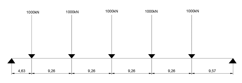
GA_f6p48n.png
.

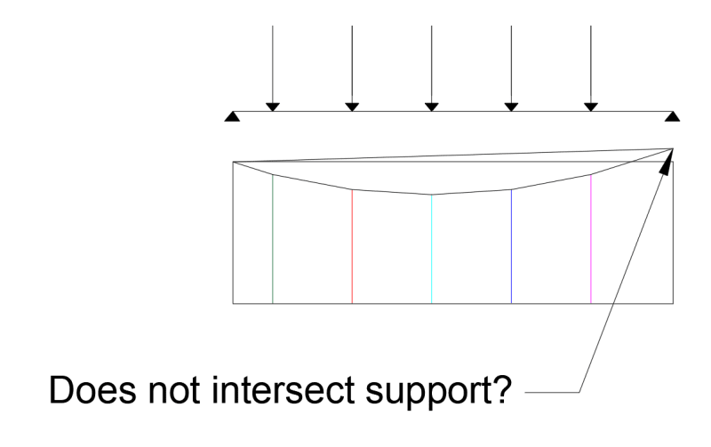
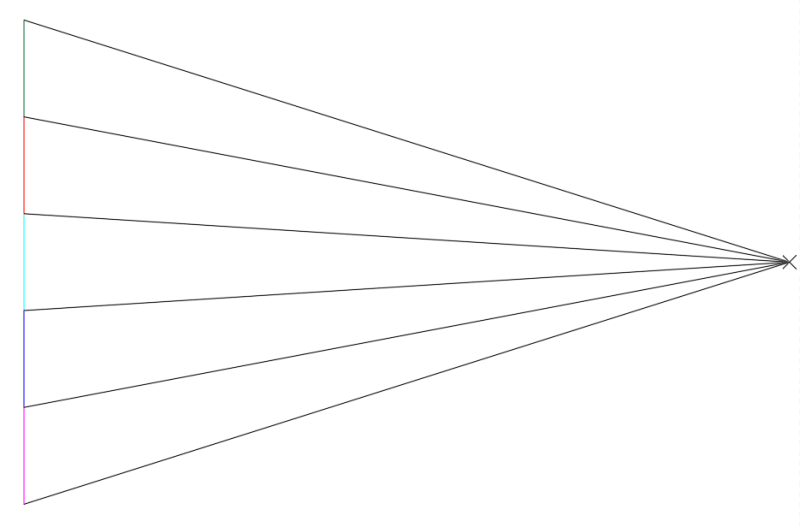
I made an attempt at drawing the funicular polygon...I followed the steps:

1. Draw the force vectors tip to tail (and to scale).
2. Define an arbitrary pole point
3. Connect the tip and tail of the force vectors to the pole to form the force diagram
4. Transfer parallel lines to the form diagram
Funicular_g14vn4.png


Pole_pk80fz.png


My question is, no matter where I draw the pole, I cannot get the funicular polygon to intersect both the left and right hand supports? Surely it must intersect these points as the funicular polygon represents the deformed geometry of a cable fixed to these supports?

Is there something obvious I am doing wrong in the formation of the funicular polygon?

Thanks in advance for any help!
 
Replies continue below

Recommended for you

isn't this just 5 load vectors down and 2 reaction vectors up ?

"Hoffen wir mal, dass alles gut geht !"
General Paulus, Nov 1942, outside Stalingrad after the launch of Operation Uranus.
 
perhaps not ...

Screen_Shot_06-30-23_at_11.15_AM_ifc9me.png


but I don't understand it, and this example is easy to solve with math. (I liked the "soviet encyclopedia" reference, and the potential for "ideologically biased")

"Hoffen wir mal, dass alles gut geht !"
General Paulus, Nov 1942, outside Stalingrad after the launch of Operation Uranus.
 
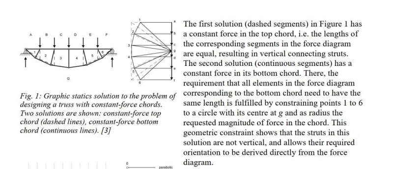
The sketch below indicates the force diagram for a truss with constant force in either the top or bottom chord. In this case, it's a cable pinned at each end, so it is equivalent to the truss with top chord having constant force (or the horizontal reaction at each pin). So we are looking at the dashed lines in the sketch.

Capture_vcprel.jpg
Capture_vcprel.jpg


Not sure why there are two copies, but for the full article, see:

 
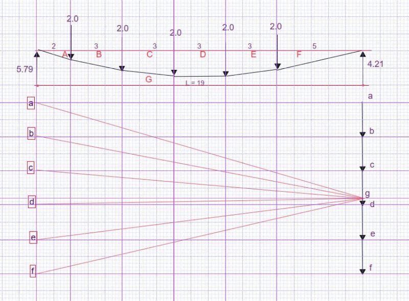
Below is a similar arrangement to the OP. Loads are each 2 (units not important). Red uppercase letters indicate zones. Black lower case letters in red box when connected with point g on the right are vectors (scale dependent on maximum sag).

Reactions are 5.79 and 4.21 for R[sub]left[/sub] and R[sub]right[/sub] respectively. The drape of the cable, to an unspecified vertical scale, is geometrically identical to the moment curve of a beam spanning 19 length units. Points a through f are separated by 2 force units. Point g is not arbitrarily placed; it is located 4.21 units above Point f.


Capture_whhxzc.jpg
 
Hi BAretired,

Thanks for taking a look at my post. It seems like you have been able to close the polygon at both supports.

I will try to replicate your method with my problem!

I wondered why the position of the pole is not arbitrary, could you explain any further?

Thanks,
 
so is this a tool to determine deflections, knowing the reactions ? (it seems you needed to know the 4.21 RH reaction)

"Hoffen wir mal, dass alles gut geht !"
General Paulus, Nov 1942, outside Stalingrad after the launch of Operation Uranus.
 
willowman said:
I wondered why the position of the pole is not arbitrary, could you explain any further?

Certainly. The vectors at the right represent all of the applied forces and the two reactions. You must first calculate the reactions, which are independent of the sag in the cable. The vector sequence abcdefga shown at the right of my force diagram must add up to zero to satisfy equilibrium. It does because it ends at the point where it started, namely point a. Vector ab is drawn as 2 units downward and represents the applied load between zone A and B. Same with B-C, C-D, D-E and E-F.

Vector fg represents the right reaction, which I found to be 4.21 units. Vector ga represents the left hand reaction which is 5.79 units. The reactions add up to 10 units, which corresponds with the applied load 5*2.0 = 10 units, serving as a check on my arithmetic. So point g is located at 4.21 above point f and 5.79 below point a.

There is one dimension which is totally arbitrary, namely the horizontal force H in the cable. The magnitude of H depends on the sag in the cable, which is not specified, so my sketch, if drawn to scale, has a maximum sag in Zone D which appears to be about 1.4 length units. If the expected maximum sag is, say 2.8 units, then the horizontal dimension of the force diagram should be one half the dimension shown. Accordingly, the value of H would be half the value measured on my sketch, and the slopes would all be larger.

I hope that clarifies the method, but please let me know if there are further questions.
 
of course, maximum deflection is not at a load ...

"Hoffen wir mal, dass alles gut geht !"
General Paulus, Nov 1942, outside Stalingrad after the launch of Operation Uranus.
 
rb1957 said:
of course, maximum deflection is not at a load ...

I'm not sure of your point, but maximum deflection of a cable with concentrated loads must be at a load. Could be at two adjacent loads with a horizontal length between.
 
ok, a cable ... I was thinking of a beam.

oh wait, OP says "but the spacing along the beam" ... so (generally) on a beam max deflection is not at a load (unless special symmetrical loading).

now maybe this method is representing the beam as a cable (as being "near enough") ?

"Hoffen wir mal, dass alles gut geht !"
General Paulus, Nov 1942, outside Stalingrad after the launch of Operation Uranus.
 
BARetired, thanks for the additional explanation. It is clear to me now.

I wondered if you could advise how the situation would change if all of the loads were inclined but remained parallel to each other?

Can the same analysis technique be followed as for the vertical case?

Thanks in advance,
 
Hi desertfox,

I came across this paper previously and I struggled to apply the method to a pinned-pinned beam. The inclined load examples in the paper are applied to simply supported (pin-roller) beams.

Thanks for the input :)
 
Hi willowman

You’re very welcome

“Do not worry about your problems with mathematics, I assure you mine are far greater.” Albert Einstein
 
willowman said:
I wondered if you could advise how the situation would change if all of the loads were inclined but remained parallel to each other?

I have never used the graphical method to solve an indeterminate structure, and a pinned-pinned beam is one degree indeterminate, but here is what I think would result:

The five horizontal components, F[sub]h[/sub] would affect the end horizontal reactions; so that H[sub]l[/sub] +H[sub]r[/sub] +5F[sub]h[/sub] = 0. They would affect axial stress in the beam but would produce no moment if applied at the neutral axis. Since the beam cannot change length, cable forces would remain as found earlier, which means beam moments and shears would be unchanged.

Neglecting variable axial strain in the beam, the structure would behave as if it were loaded with just five vertical loads.
 
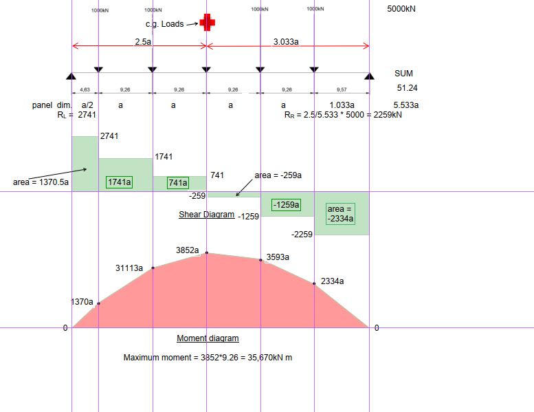
Graphical methods may be useful for complex 3D structures, but for the problem in the OP, standard methods seem to be easier to apply. The OP's beam is pinned both ends, making it indeterminate. It could be analyzed with pin/roller supports. In that case, beam reactions are both vertical as there are no horizontal applied loads.
Capture_eznali.jpg
 
Status
Not open for further replies.

Part and Inventory Search

Sponsor