Eng-Tips is the largest engineering community on the Internet

Intelligent Work Forums for Engineering Professionals

Fury 325 Rollercoaster cracking 15

Status
Not open for further replies.
Replies continue below

Recommended for you

I would suggest that the crack is what's left after the break. [ponder]

-----*****-----
So strange to see the singularity approaching while the entire planet is rapidly turning into a hellscape. -John Coates

-Dik
 
drwebb, its semantics to some degree, but in this case, based on a couple of photos or video screen shots shown above, the failure appears to have started as a crack at the weld and grown into a full section break.
 
It appears from the video that the cars are going up and then going down as they pass the support. That's going to create a lifting effect that reduces the contact pressure between the broken parts which allows them to slip sideways more easily. I wonder if looseness in the nearby bolted joint could have contributed to the failure.
 
A great number of buildings have collapsed without FEA. I'd expect the majority of collapses have never been near an FEA.

What I have seen in FEA is that local stress concentrations arise from the exactly sharp nature of the elements.

On one project we spent a huge amount of money in 17-4PH, 10,000 pounds of it, including the post-weld heat treat because the FEA showed some sharp stress concentrations. Turns out those almost instantly yield plastically and would not form cracks so a far cheaper alloy was used on production items. AFAIK, no design change and no cracks.

tl;dr FEA is more likely to result in an over-report of stress.

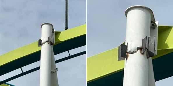
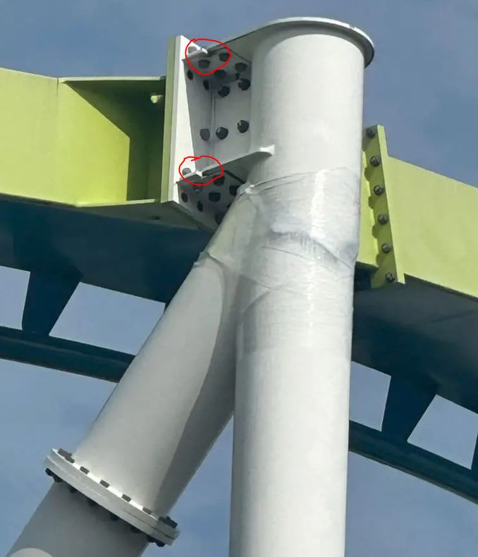
This looks like someone overlooked a major load case or the load case wasn't including all the factors; probably that the uplift from the roller coaster car was determined but not the torque applied via the rails. Perhaps they overestimated the torsional resistance of the curved box beam? FEA wouldn't but hand calcs might.

It also looks like what I've come to call - the can opener. Where a stiff section ends in the side or face of a flexible element the stiff end acts to punch into the flexible element. There needs to be significant reinforcement to avoid the start of a fatigue crack.
 
Fury_325_fix_fzyzfi.jpg


It looks as though they have welded some (hopefully) temporary plates across the crack in the support column.
 
sgq1009 said:
It looks as though they have welded some (hopefully) temporary plates across the crack in the support column.

Ugh. Why bother? If they were genuinely worried about it falling off prior to the repair then some heavy duty straps would have been neater.
 
"safety is top priority"
These days the priority has shifted to looking for people going crazy, or shootings.
Mechanical safety checks of rides have lessoned in the past few years. I have met guys that are supposed to do it, but they are told to do quick checks and not take long. Management wants the ride moving, time is money.

Chris, CSWP
SolidWorks
ctophers home
 
I wonder how things would have worked out if that area had used a sliding shoe, like on a bridge.

Maybe they made all the joints too rigid?


spsalso
 
From New Yorker article about the Titan submersible:

“Safety is our number one priority,” Rush said, in an OceanGate press release.

Interesting correspondence in language. All apparently drinking the same Kool-Aid.

Regards,

Mike


The problem with sloppy work is that the supply FAR EXCEEDS the demand
 
I wonder if the geometry is part of the problem. The inclined diagonal ties in just under the point of application of the load. That little piece of column above the diagonal workpoint is being asked to do quite a lot. It's not concentric, so it sees some flexure, but it's not a long enough cantilever above the workpoint to allow much in the way of "flexibility". I'm sure if we looked at the actual wall stresses in that little piece of pipe at the top there are some weird things going on there.
 
It's a joint. There is a fitting welded bolted to the rail, a fitting welded to the support, and splice plates joining those two fittings. What is circled is a chamfer on the corners of the fittings.
 
Status
Not open for further replies.
Back
Top