Eng-Tips is the largest engineering community on the Internet

Intelligent Work Forums for Engineering Professionals

  • Congratulations waross on being selected by the Tek-Tips community for having the most helpful posts in the forums last week. Way to Go!

Fuselage Hoop Stress Calculation 1

Status
Not open for further replies.

rmmoraes

Structural
Oct 2, 2019
7
0
0
US
We had a discussion in our group on how do the hoop stresses are calculated in a fuselage section composed of different radii (non circular shape).
Do you use the biggest radius (being conservative)?
Do you use the local radius for a given panel?
Do you use the opposite radius of the panel you are calculating?
Do you use an average of radii?

Which method is the most broad and complete one that we could rely on and give away the conservatism when needed.
Do you know any methodology or a paper with a methodology?

Thanks in advance for any feedback.
 
Replies continue below

Recommended for you

using the local radius is probably most accurate.

Becarefull about assuming there is an obviously conservative approach. Non circular fuselages have significant secondary effects (in the frames). The floor support beam is also a source of stress trouble.

another day in paradise, or is paradise one day closer ?
 
Thanks for your feedback rb1957!

Yes, indeed non circular fuselages cross sections promotes secondary effects, but the uncertainty itself is specifically about the theoretical hoop stress (P * r / t). In a circular fuselage there is no issues...r is the radius...case closed. But in a non circular fuselage cross section with 3, 4 different radii along its perimeter. What should be done? Taking the biggest radius will cover for everybody, but sometimes it is too conservative. From there the discussion was generated...what should we use to avoid being too conservative? Is there a methodology to calculate theoretical hoop stress for non circular fuselages?
 
as I said the simple thing would be the local radius at the point of concern. The obvious issue is what happens at the transitions. Here the frames will have to absorb the change in force directions, and there'll be some "funky" bending (and yes, that is the correct technical adjective !??) on the stringer along the transition.

One thing you'll see is the pressure vessel skins will try to conform to some common radius (like the height of the fuselage/2). The skin panels will deflect out-of-plane (slightly) and the frames will have "funky" bending.

another day in paradise, or is paradise one day closer ?
 
Another approach is to go to the proof in calculus that shows how the stress can be expressed as the integral of the "da" segments of arc. Instead of integrating around the entire circle, only integrate from angle 1 to angle 2 for each lobe. Do the same for the other lobe(s). Michael Niu's textbook gives you the integral. His approach is probably based in Timoshenko's work, but that's just a guess. This will also give you all the unbalanced forces at the joints between each segment of arc.
If you remember your calculus, and have a copy of Roark for the joints, you'll be done in an hour or two (all too quickly, I'm sorry).
If you want the fun to last, you can do as SWComposites suggests. You will still be fussing with the model days from now. Enjoy!


Your equation (P * r / t) is valid only for constant radius. Using local radius is not correct IMHO. To be certain about that just imagine there is a flat spot in the section (r=0). How does this formula work in this case?
 
actually a flat is R = infinity, and yes hoop stress doesn't apply to a flat surface; although a flat surface will deflect under pressure, creating a curved surface ...

I Know that this is done (by OEM) for a bi-lobe fuselage. Where this works for an oval fuselage was a guess. Ultimately the oval fuselage will deflect to a circular shape (if there's not preventing it from doing this, like frames and tie-beams) with, I expect, and equal circumference.

another day in paradise, or is paradise one day closer ?
 
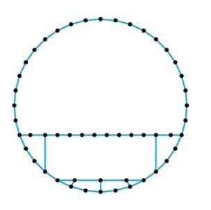
If you do want to use FEM, you can try the 1D Elements program linked below. There is an an example file called "fuselage frame" as well (corresponding to the picture). For arbitrary shapes, you can use the NodeMaker program and just pick the nodes on the screen. You could also compare the results to classical solutions.


frame_gzjtee.jpg


Brian
 
Status
Not open for further replies.
Back
Top