Continue to Site

Eng-Tips is the largest engineering community on the Internet

Intelligent Work Forums for Engineering Professionals

  • Congratulations KootK on being selected by the Eng-Tips community for having the most helpful posts in the forums last week. Way to Go!

Gable Frame w/o vertical 1

JStructsteel

Structural
Aug 22, 2002
1,352
Got a ridge beam on a open deck that comes into end beams. Owner does not want a vertical post in the middle. he is ok with a tie at the bottom.

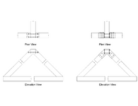
Playing around with details, I have come down to 2 options. Left is just tie bolts holding everything together, right is a saddle plate weldment for the connection. I know the best is the plates, but are there any other options? Maybe slots in the beams and a knife-flitch like plate hidden?

Load from ridge beam is about 6K, so not huge, but enough that I dont like the left one.

Thanks
Ridge Beam.png
 
Replies continue below

Recommended for you

I don't like the left detail. I doubt it would calc. out with 6k.

The right detail seems ok. I would probably use an alternative connection, though, with the top chords butted together with a flat top aligned with top of ridge beam, and a top mount connector (either Simpson or fabricated from 1/4" steel plates) to support the ridge beam.
 
Try detailing the rafter to ceiling tie connection and get back to us. That is the hardest part - with a 6k ridge load.
 
Try detailing the rafter to ceiling tie connection and get back to us. That is the hardest part - with a 6k ridge load.
Thanks, good point. I will probably have steel down there too, but yes, getting anchors to work. Could always have a steel strap on top of the beam.
 
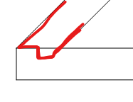
For the base connection I have sometimes done this with a notch so that some of the tie force can be taken out in direct end grain bearing like below. If that's not enough then you need to add some steelwork. Can you not make the top connection work as with the left detail. I would only have a single bolt through as those double bolts don't have a lot of edge and end distance. The bolt is only there to tie things together and doesn't have any calculable force in it. Here again you are relying on the bearing of the ridge beam on the bit of rafter. If the bearing length is not enough then you could use a steel plate to widen it.
1730825138642.png
 
They never like the vertical posts in the middle, but it is so much better if you are in an area with snow. Sell them on the fact that they can add some decorative webs on either side to make it a nice looking truss. It's up 8+ in the air anyway, it's not like vertical stub post is going to block anyone's view.

As XR said the heel connection is difficult with this type of design.
 
This load, without any dimensions, seems unworkably large. You need a vertical.

And that notch detail screams no testing and cross grain tension or splitting. That looks like a cabinetry detail. Or Mortise and Tenon which I depends on generally large sections and lower forces.
 
I usually just make 'em run a vertical all the way to the foundation. Although, i just finished one similar to this but it was only 2k - so much easier.
Trying to resolve 6k in the unbraced horizontal beam is going to be difficult.
 
This load, without any dimensions, seems unworkably large. You need a vertical.

And that notch detail screams no testing and cross grain tension or splitting. That looks like a cabinetry detail. Or Mortise and Tenon which I depends on generally large sections and lower forces.
yes, the left detail is out. steel detail works at the top. At the bottom I think I will need some steel rods or strapping to take the tension.
 
I usually just make 'em run a vertical all the way to the foundation. Although, i just finished one similar to this but it was only 2k - so much easier.
Trying to resolve 6k in the unbraced horizontal beam is going to be difficult.
Straight down to the foundation is not an option.

The bottom of the beams will end up in a steel weldment too, so the steel is taking the thrust. More than likely tension straps each side of the wood across to the other corner.
 
There are plenty of connection options to get this to work using steel. I've often used a steel saddle type connector where the top chord is bearing directly on the steel and steel side plates and thru bolts provide the connection to the bottom chord. A pair of side plates even without a saddle would probably work although I like having direct bearing.
 
They never like the vertical posts in the middle, but it is so much better if you are in an area with snow.
It's a zero member, other than self weight and part of the bottom chord...
 
Can you hang the ridge onto the wall-truss using a hanger? Perhaps a simlar to a Simpson CBH or the euro originals that it is a copy of?

Regarding the frame and its connections, mortise & tenon connections can often work well. Below example was buried in the wall and is therefore PSL. I was concerned about the feasibilty of chipping out the joinery in PSL, but the contractor said it worked quite well.
Untitled.png
 
It's a zero member, other than self weight and part of the bottom chord...
It's a zero member if you can somehow resist the forces at the bottom of the gable end forces. But a H2.5A hurricane clip ain't going to cut it so it's best to just use a structural ridge and post down.
 
It's a zero member if you can somehow resist the forces at the bottom of the gable end forces. But a H2.5A hurricane clip ain't going to cut it so it's best to just use a structural ridge and post down.
The whole point of this discussion is not to have a middle post.
 
I am aware, but as I mentioned above, no one ever wants the post at the beginning. But it's typically not that hard to sell someone on it, particularly because it will be above the sight lines and they can make it decorative enough to blend into the design.
 
Maybe look at doing purlins instead of a ridge beam. Should make the reactions/connections a little more manageable and the top chord members can just butt together at the peak like in @Craig_H’s detail.
 
Maybe look at doing purlins instead of a ridge beam. Should make the reactions/connections a little more manageable and the top chord members can just butt together at the peak like in @Craig_H’s detail.
The ridge beam is needed for the SIP panels. I can look into framing the ridge into the sides of the end beams.
 
You should be able to cantilever the SIPS and butt them at the peak. See here: https://portersips.com/downloads/Details/RoofDetails/R9.pdf

Similar to this:

head-timber-framers-1.jpg
 

Part and Inventory Search

Sponsor