Eng-Tips is the largest engineering community on the Internet

Intelligent Work Forums for Engineering Professionals

gabled patio cover - ridge beam support sanity check 2

Status
Not open for further replies.

alo53

Aerospace
May 9, 2022
10
0
0
US
Hi - looking for a sanity check on the load path / sizing of one of the members on a patio cover we had designed and are about to build. I am an aerospace engineer with structural design experience in that field, but not in building design and construction. The design is a gabled outdoor patio structure with large beams.

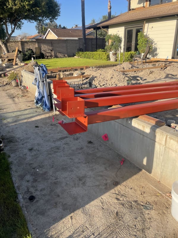
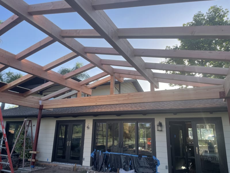
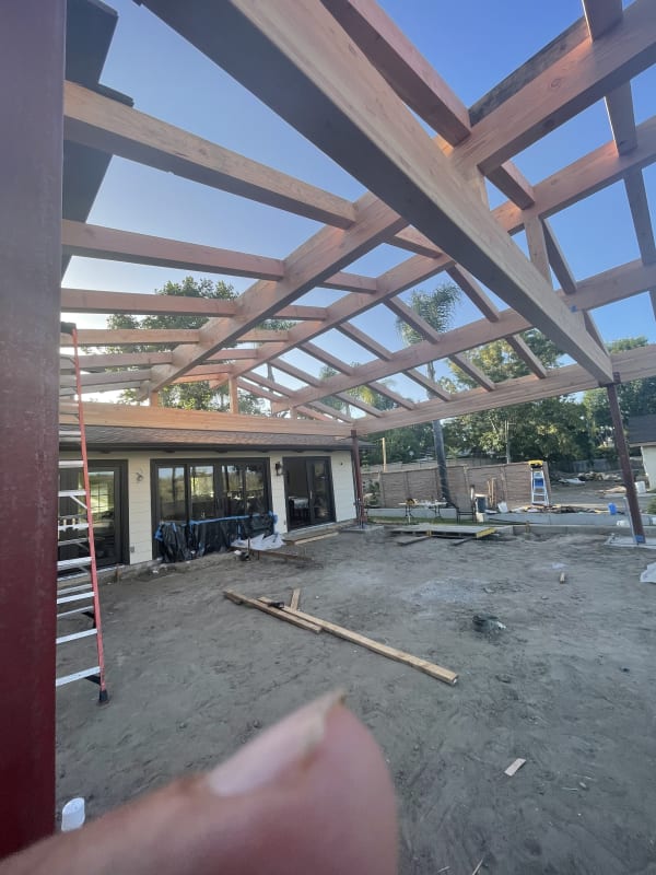
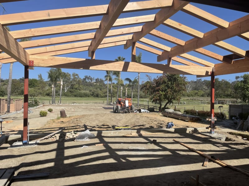
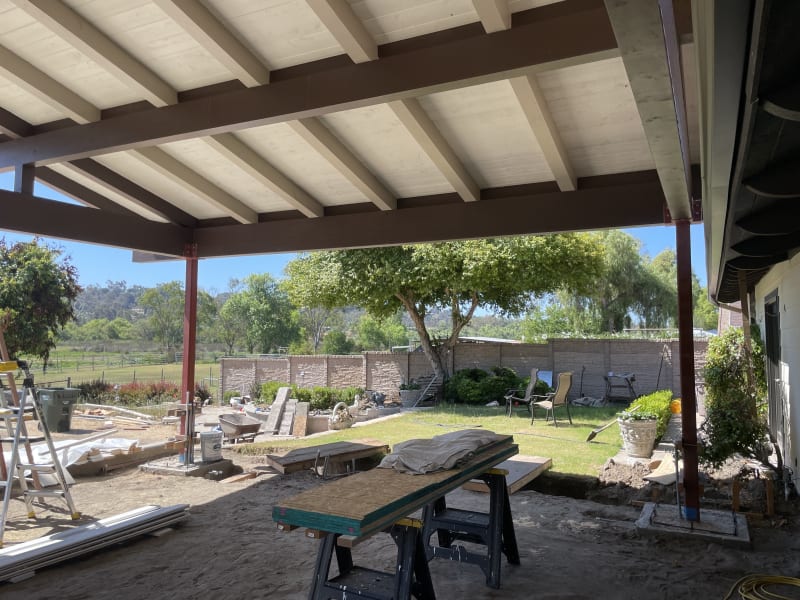
The ridge beam is designed as a 6x14 DF#1, supported by an arched ridge support beam / collar tie that is tied to the rafters and queen posts by 5/8 lag bolts. The span between queen posts is about 12 ft, while the span between where lag bolts can tie the beam to the rafters is about 6 ft. The beam just feels undersized and insufficiently supported to me but the engineer working on our project assures me it is not. I just wanted to see what others think and if I should challenge it any further. Any reassurances would be much appreciated :)
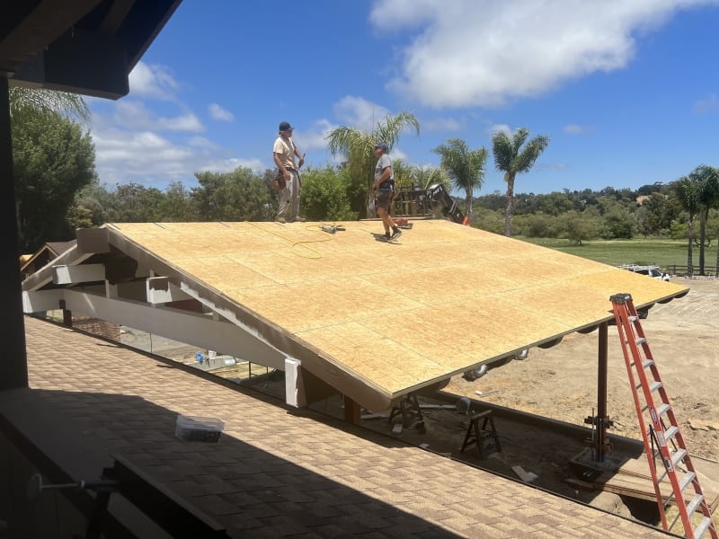
. i have been having fun with this project, we actually have all the steel columns erected already and we are almost ready to purchase all the lumber.

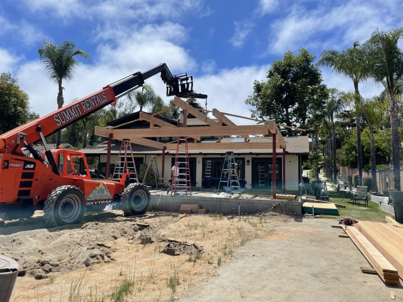
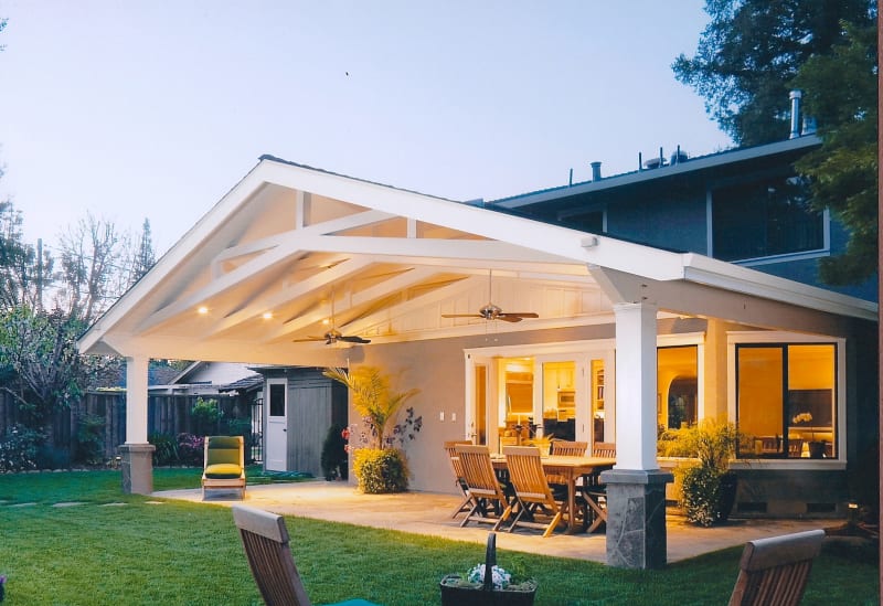
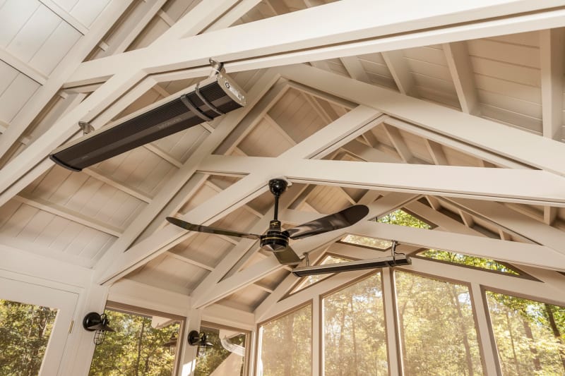
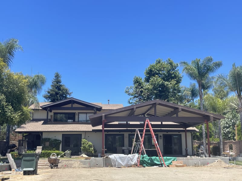
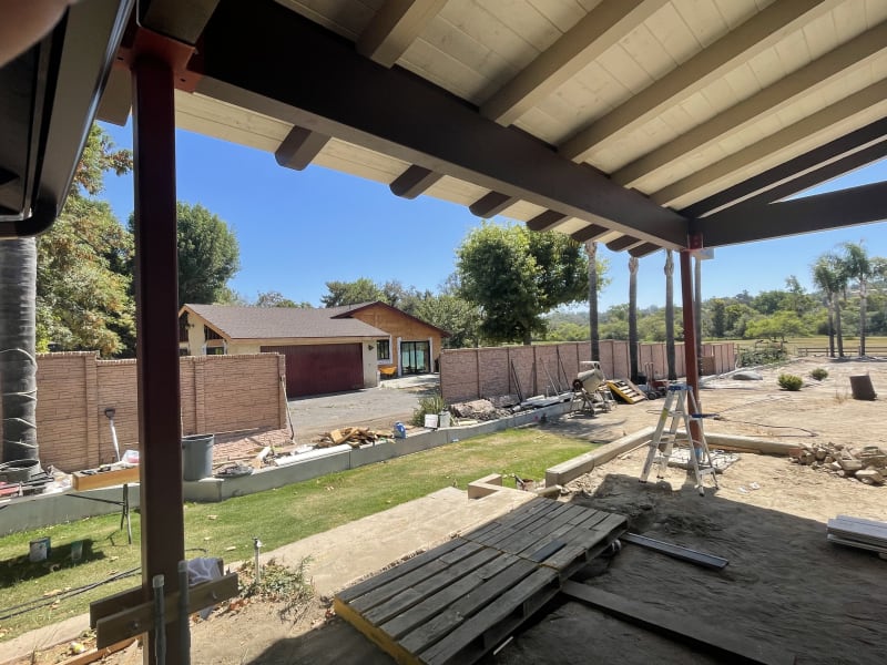
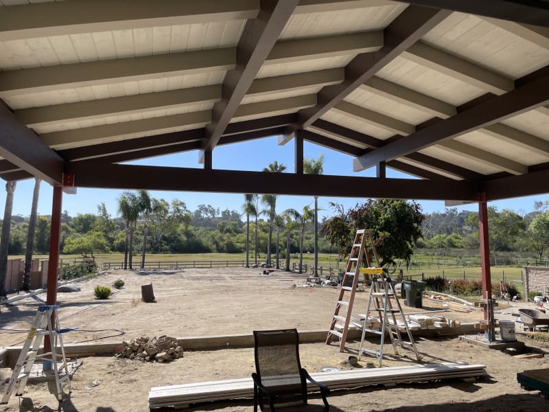
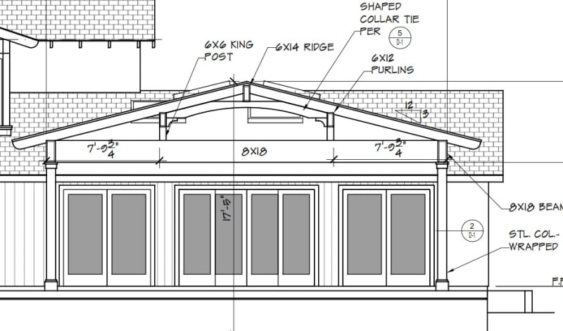
Here is a picture of what the structure will look like:
patio_design.png_ct1klb.jpg


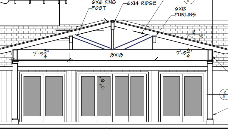
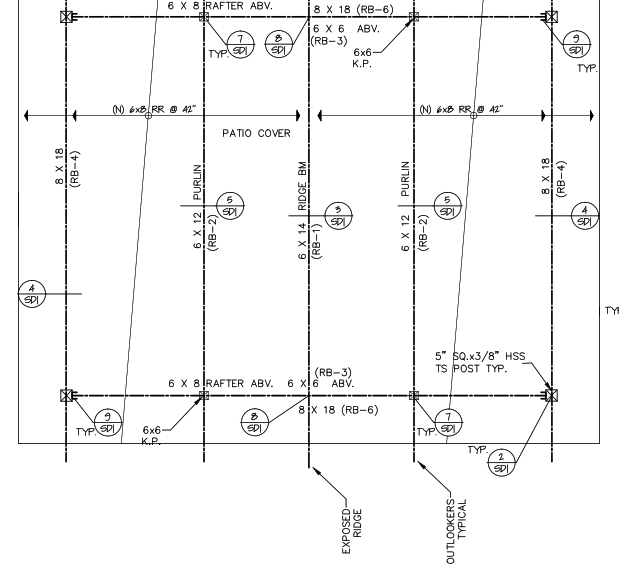
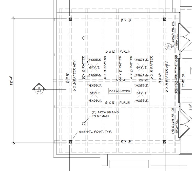
here is the structural layout
patio_design_struct_kfsjf6.png


here is the dimensions of the beam in question:
collar_beam_vyofxe.jpg


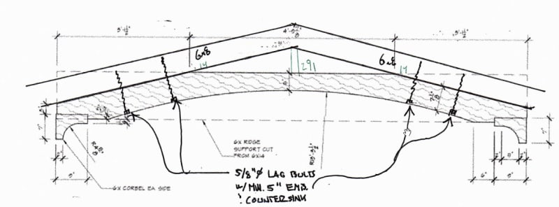
here is how the engineer specified connections to the 6x8 rafter
collar_tie_rafter_zzavjx.jpg


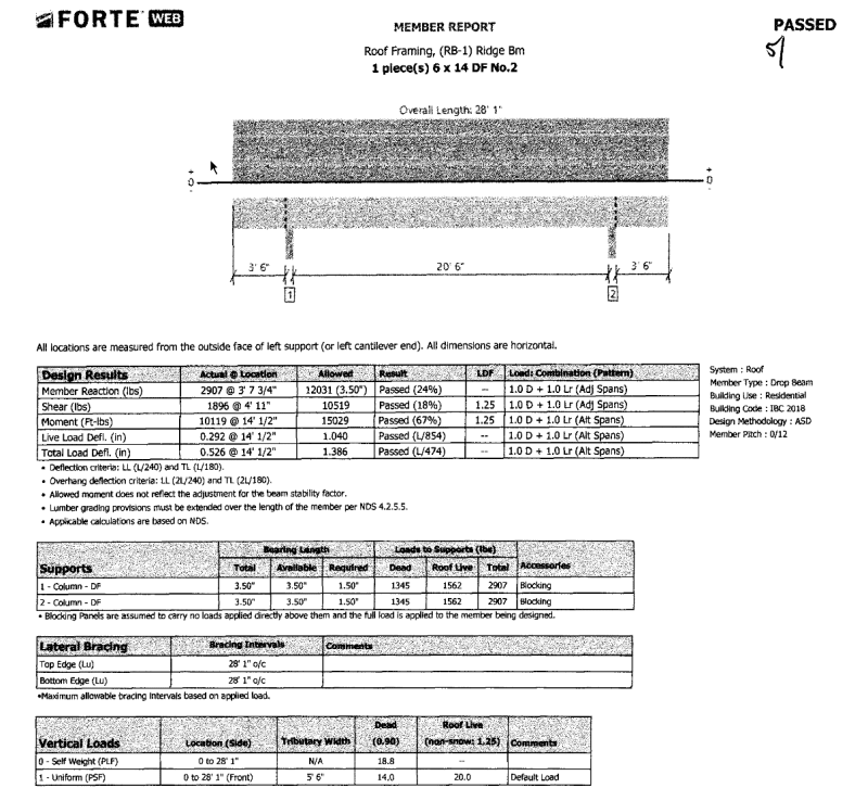
here is the analysis on the ridge showing the reacting loads:
ridge_ypd7um.png


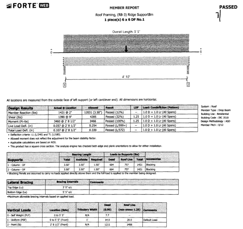
here is the analysis on the ridge support showing the reacting loads. Note the assumption of span in this calculation, it is assuming the span is the distance between where the collar tie touches rafters and where we can get a lag bolt in:
ridge_support_ih1tcq.png


here is another sketch:
patio_design_layout.png_otdgyz.jpg


another question i am trying to wrap is the ridge beam is supporting the last part of the span of the rafters, which is supporting the ridge support, which is obviously supporting the ridge. is this some sort of unstable feedback loop?
 
Replies continue below

Recommended for you

It does look sketchy. Probably the easiest way to have handled that was to cantilever the rafters from the side beams and not even use a structural ridge.
 
I don't love all the notches and radius cut in that beam. Back "in the day" when stuff like that was done regularly by skilled craftsmen in buildings (or ships), they'd often seek out just the right piece of lumber (or branch in an existing tree) that followed the curve naturally. That way, when the board was milled, you still had a continuous grain pattern and superior strength. Today, somebody's going to take any ol' 6x14 and cut it to shape with no regard for the grain pattern. You'll end up with some interesting grain discontinuities and potential fracture points in the beam.

Not saying it'll happen, but whatever grade the engineer is assuming that beam will be...well it won't be unless it's carefully selected and inspected after it's been cut to ensure it meets the specs for whatever stress grade was assumed.

I'm also not a fan of the lag screws in tension in a wet environment holding up most of the roof.

I agree with XR - increase the purlin size, cantilever the rafters, and put the rest of it in (if you want it) for decoration.
 
I’m sad that you guys have the same gut feel as I did, I was hoping it wasn’t a problem. I was already going to have the contractor cut to a min thickness of the arched beam to 8 inches instead of 5 due to it just feeling undersized


Pardon my amateur question, but with the cantilevered proposal, how would that connection look? Would it be at the purlin? And with what sort of connection?

Is another alternative just putting a king post under the ridge beam, eliminating the arch, and putting a couple diagonal beams between bottom king post and queens/purlins? I believe the large horizontal beams are already sized big enough to take the load.

 
@JLNJ
lateral loads supported by steel columns which are 5x5x3/8 thick HSS structural steel with bottom 3 ft of column and base plate embedded in 3 ft of reinforced concrete and bolted to a footing. top of columns have CCT column caps welded on.

steel columns were already delivered, picture of the buckets for the beams to sit on
beams_koef1q.jpg


footing locations (footing is 3 ft embedded in future concrete pour)
IMG-4316_2_cmydao.jpg
 
You'll have to define "nicer." Looks like a nice Howe truss to me. You could get fancy with the joinery if it's exposed, or use decorative plates. That might dress it up a bit.
 
What about a steel angle on top of the decorative piece, and then bolted thru (or lagged) into the 6x8's from behind

Or instead of the lags shown, thru bolt into a recessed hole and cap.

I would talk it thru with the engineer and contractor, voice some of these issues, and get something built you feel comfortable with.
 
C062ABBB-FE98-465B-857B-A598EAD51092_ztegei.jpg


7C3DD1FF-020C-4B41-9A2F-459318C7D763_kuyrvw.jpg


We ended up getting approval from the engineer to add a king post and that’s it. We will probably add a decorative collar tie as well. The framers knocked out putting up all the big beams in a day. We installed the steel columns and footings ourselves last month

Thanks everyone for the input and discussion. I wanted to feel safe under this thing
 
THIS IS WITHOUT CROSS BRACING ?
I think this is tend to sway either side easily ...
use side panel asap to prevent side movement
failure will occur at bolts reign [column heads attached to beam]
just my opinion
 
The picture was taken during middle of construction. On top of the beams is gonna be heavy duty 6x8 rafters tied to the beams with some heavy duty screws and connected over the ridge with heavy duty straps and blocking / sheathing over the entire roof.
 
@ alo53
even in/during construction stage Temp bracing is essential [with some cable and turnbuckles ]
bolts [attached to wooden girder] tend to slip/rotate easily due large sideway movement
Also heavy weight of roof frame is critical
best choice will be circular HSS with larger diameter [and less wall thickness]
Knee bracing is also add [plus] value to your structure
and thanks for the answer [best of luck...]
 
Cantilever columns, and determined previously in the thread, are an acceptable lateral system that would likely reduce the requirement for temporary bracing.

I love heavy timber type buildings. Nicely done.
 
3DCE3EE5-63B7-46BD-B506-C4E55C37B144_eewy5q.jpg
47EA301E-6B12-4C18-812B-CF925A0F9734_w9gryr.jpg
0062635B-E0FD-49E8-9980-F65BEF21F7A9_pib8iz.jpg


The carpenter working on our project is ultra talented. We are super stoked how it is coming out. Before this framing we did all the work ourselves (reframing the house and doors, foundation, siding, and steel columns)
 
Obviously, you're already well underway... but was there a reason that scissor trusses weren't considered? Uplift, lateral, etc?

Thinking that would've alleviated some of the issues with your ridge beam feeling/looking a little slim.

outdoor-rooms-clayton-nelson-and-associates-img_b9e14f8e01a51bfd_14-5878-1-3405b08_htvjda.jpg


cathedral-ceiling-corinthian-fine-homes-img_40b1340702b06845_14-2265-1-c25d5aa_d2ezdp.jpg


images_uaq6jd.jpg
 
Status
Not open for further replies.
Back
Top