Continue to Site

Eng-Tips is the largest engineering community on the Internet

Intelligent Work Forums for Engineering Professionals

  • Congratulations SSS148 on being selected by the Eng-Tips community for having the most helpful posts in the forums last week. Way to Go!

Gambrel Roof with a Stick Built Moment Frame

Status
Not open for further replies.

medeek

Structural
Mar 16, 2013
1,104
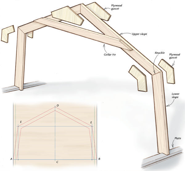
This one is looking to be an interesting project. The client wants to stick build the roof in a similar fashion to the method detailed by Andrew DiGiammo in the Journal of Light Construction:
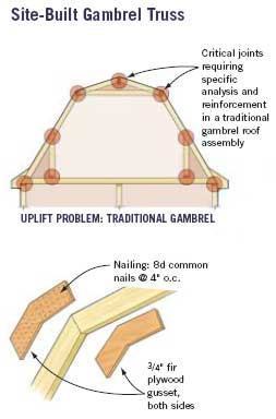
The method is similar to a site built truss in a lot of ways using 3/4" plywood as gusset plates as shown below:

gambrelframe2_mtp5zr.jpg


gambrelframe1_wdmuvf.jpg


I haven't got into all of the details yet but just poking around the internet I've found some interesting articles etc...

I will provide further structural details as I progress but for now I'm just wondering if anyone else has looked at this type of system before?

I will probably put this into Risa3D to determine my moments, axial and shear of the members at the joints. This is a very similar problem to analyzing a site built truss. Here are some basic assumptions and initial thoughts:

1.) The floor joist will be loaded in tension, preventing the frame from speading its legs, in essence the bottom chord of the truss. Check this member for combined tension and bending due to floor loading.
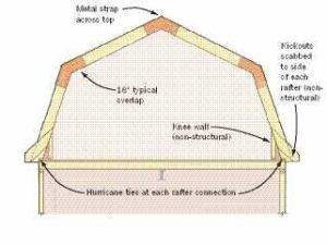
2.) The connection at the floor joist (I Joist) and the bottom of the frame will be assumed to be pin jointed with attention to the uplift and tension at this joint. I'm thinking a sill plate that the 2x12 or 2x10 lower rafter is notched into might provide a nice positive connection for the outward thrust of the roof. I'm still thinking about uplift and what ties to use at this location.
3.) 3/4" plywood gusset plates will be at three locations. Tension and Moments at these locations will control the design of the gusset plates and fasteners. The debate of single shear vs. double shear nailing continues. The large gusset plates will create rigid joints at these locations.
4.) Check the the upper and lower rafters in combined compression and bending.
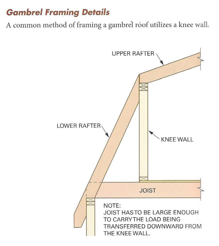
5.) The client will probably install a knee wall and a collar tie, how does this affect the analysis.
6.) The floor joist will be supported at approx. mid span by a bearing wall on the first floor.
7.) Need to look into wind loads on gambrel shaped roofs, this one is new for me.

Just a few things to get started with, I'm sure there will be other questions, assumptions and issues with this design.

A confused student is a good student.
Nathaniel P. Wilkerson, PE
 
Replies continue below

Recommended for you

Ok....is there a question here or are you just being helpful?

Check out Eng-Tips Forum's Policies here:
faq731-376
 
JAE,
It is curious how part of a post shows up, then the rest. Don't know if it is a site glitch or if the OP did it, but I have seen it recently in another thread.
 
Here is a better depiction of the basic construction I'm looking at. Note the sill plate at the bottom of the lower rafter. Also the collar tie allows the geometry of gusset plate at the peak joint to take on a more general shape which is not constrained to the outline of the rafters. The client would prefer that the other gusset plates do not extend into the space if possible.

gambrelframe3_x6yjvz.jpg


Just for comparison purposes it would be interesting to model the frame with and without the collar tie to see how it affects the loading at the joints and the bending in the members, which of two will be more conservative? With the plywood gusset plates large enough can the collar tie be omitted entirely?

A confused student is a good student.
Nathaniel P. Wilkerson, PE
 
hokie66 - note that the posts have been edited.

Check out Eng-Tips Forum's Policies here:
faq731-376
 
With a collar tie as shown in the second pic, these are stable without all the gusseting as long as you have a sufficient roof diaphragm and gable end shearwalls. It is no different than the rectangular frame of the story below which uses the ceiling diaphragm and endwalls to give it stability. The top pic does require gusseting.
 
@XR250

I would agree with this assessment provided that there is a continuous chord (ie. double top plate) framed in at the pitch change of the gambrel roof. If you look at framing texts that show how to frame a gambrel roof, the old school method typically has knee-wall coming up to the pitch change and then rafters (upper and lower) supported on this knee-wall.

With the alternative method I've shown there is no continuous top plate (chord) at the pitch change. My theory is that each "truss" bay will act like a moment frame similar to a moment frame steel building design. The lateral load from these moment frames will then be transferred into the floor diaphragm below which will then be picked up by the first floor shearwalls. Therefore each frame will need to be able to resist the lateral loads being applied to it.

There will be certain amount of redundancy since the gable walls will provide some shear wall capacity in my opinion, but without the diaphragm chord at the pitch break I'm not sure I can rely fully on the gable end shear walls to take all of the lateral load (transverse).

The problem with the old school method of framing a gambrel roof is the way in which the vertical loads of the roof are transfered into the kneewall and then into the floor joists below. Since the knee-wall in inset from the exterior wall it imparts significant bending into the floor joist below.

The method shown above should more successively transmit those vertical loads directly into the perimeter walls below.


A confused student is a good student.
Nathaniel P. Wilkerson, PE
 
Typical gambrel framing using traditional method:

GAMBREL_FRAMING_dzcqa2.jpg


With wind loads in the longitudinal direction (parallel to ridge) the steep lower pitch will act similar to a shear wall in preventing racking.

A confused student is a good student.
Nathaniel P. Wilkerson, PE
 
Good point about the chord. The traditional method is easier and provides the chord - win win
 
Medeek - How do you analyze the plywood gusset moment connection? Wood is not my specialty and I was looking at this same article that you referenced not long ago for a similar situation that I have. The article does not go into the details of the moment connection design. The author states that 2-3/4" gussets are the same thickness as the framing and must be adequately nailed - this makes me wonder if his analysis is not very robust. Do you have any add'l info on such a design?
 
Agreed, they don't really get into their analysis in the paper. My first step will be to create a model in Risa3D. I will then assign the gussset joints as fixed whereas the connection at the base of the roof assembly will be pinned. I will need to generate multiple load cases, specifically the snow loading (balanced and unbalanced) and the wind loading (MWFRS and C&C). The C&C wind load case will be used to design the member and gusset plates and the MWFRS will be used for uplift, this is pretty typical, see any truss shop drawings where the load cases are exposed.

I will then be able to determine my worst case moment loads on the gusset plates. From there one needs to check the fastener withdrawal (shear) due to the moment (and possibly combined tension load if there is a significant load reversal from the wind loads). One also needs to check the potential failure of the gusset plate itself along the scarf line. Both of these items I have discussed in some detail in this previous thread:


If one ignores the compression load (assuming load is transferred through contact of 2x rafters) then my previous equation for the applied stress on the gusset plate reduces to: 6M/bd2 which must be less than the Ft' of the plywood.

I'm not saying this is my final algorithm, I've yet to give it more thought but I think I'm fairly close.

With regard to the shear check of the fasteners of a splice plate that is in both (tension/compression) and bending the approach would be similar to the method used in this thread for portal frames:


When I dig into it in a couple of days I will probably try to create a tidy little spreadsheet where you can enter in the results from the various load cases and the logic which determine which one will govern and control the stress analysis.


A confused student is a good student.
Nathaniel P. Wilkerson, PE
 
It surprises me that the floor joist will not be adequate to carry the roof load in the case of the "traditional" gambrel roof schematic (indicated on your sketch) when there is bearing of the floor joist near the middle of the building. Granted, you are indicating I joists and so, shear/end reaction might be an issue.

Also I realize the "traditional" approach does not provide as wide a space as you are showing. Maybe that sketch was from some other source and did not have the mid-span support as part of it.

Also seems like there would be ways to reduce the moment in the gussets if lateral stability could be achieved with a well positioned cross wall (perpendicular to the ridge) and using the roof diaphragm.

Just some thoughts. I'll be interested in your results.
 
There is an old post from 2008 asking about wind loads on gambrel roofs. I have the same question:


It seems that there is no clear direction on this within the ASCE 7-10, but I may have somehow missed it.

A confused student is a good student.
Nathaniel P. Wilkerson, PE
 
Moment connections with wood can be a challenge. Two thicknesses of 3/4" plywood do not equal 1-1/2" framing lumber. Remember that some of the plies run in the wrong direction. I don't know if there are any Fb or E ratings for plywood in bending in the manner you would be using it, but I suspect it is pretty weak. Depending upon the moments, you may also need quite a few fasteners. If you could make the gusset plates wider that would be better.

You may need more space for insulation than will fit in the required rafter depth, so increasing the rafter size would allow for wider gussets.

You could also consider steel gusset plates or talk to a truss manufacturer and so what they have to say. What you have is a frame, not a truss. When truss manufacturers build attic storage trusses (which are really frames) they tend to use large gusset plates, so truss plates may not be an option. I was thinking of thicker steel plates with bolted or screwed connections.

Double shear connections can be helpful because you do not have a lot of width to work with.
 
Status
Not open for further replies.

Part and Inventory Search

Sponsor