Continue to Site

Eng-Tips is the largest engineering community on the Internet

Intelligent Work Forums for Engineering Professionals

  • Congratulations cowski on being selected by the Eng-Tips community for having the most helpful posts in the forums last week. Way to Go!

Gap Beneath Nut 3

Status
Not open for further replies.

XPDQ

Mechanical
May 30, 2008
14
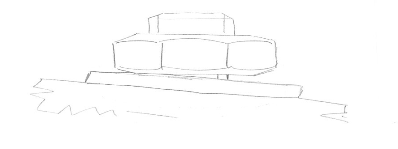
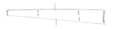
A large slewing bearing is connected with 80 rolled 1-5/8" SAE Grade 8 Bolts to the substructure of a large piece of equipment. The substructure flange that the bearing is mounted to is slightly tapered. Of the 80 bolts, 6 exhibit a gap between the nut and the washer at one extreme of the nut. The fasteners with this issue are spread out throughout the ring. The gaps are not extreme; worst case is 0.018". However, with a gap a bolt is being loaded on one side. The fastened joint is mechanical in nature, as a load is shifted when the bearing is slewed.

From a fatigue standpoint, the concentrated loading on one edge of these 6 bolts worries me. The bolts are pre-loaded at 75% of proof strength (126,550 lbf). I should also mention that all 80 bolts are regularly checked for pretension using a stud tensioner that tensions the bolt to a maximum of 157,000 lbf before relaxation back to 126,550 lbf.

Does anyone know if there is any criteria/technical justification to accept these gaps, or can anyone think of an easy solution to evenly distribute the load throughout the cross-section of the bolt?

I've looked at spherical washers, but haven't been able to find any that provide enough thrust capacity. I've also briefly looked at plain spherical thrust bearings, but the ones with large enough capacity are physically too large to be used.
 
Replies continue below

Recommended for you

Hi

What about tapered washers, these washers are typically used on the structural sections where the flanges were tapered in manufacture.

“Do not worry about your problems with mathematics, I assure you mine are far greater.” Albert Einstein
 
XPDQ:
I don’t understand what you mean with the statement “The substructure flange that the bearing is mounted to is slightly tapered.” Why and how is it tapered w.r.t. the bearing bearing surfaces? A sketch or two might help. What’s the dia. of the slewing bearing, some dimensions, bolt circle and bolt spacing, etc? Should you be shimming btwn. the bearing and the flange? Do you have any sense of what’s causing this misalignment? Are those bolts/studs bent, is the nut bearing surface messed up for some reason? What happens if you use a new nut and bolt/stud, can you pull it up tight then? I would opt for heavy washers, which my machine shop had faced or ground down with approx. the .018" slope/tapper on one surface. Have them mark the fat spot. Check the bearing surfaces on the bearing for flatness and any slope.
 
If you are looking at something alike this:
gap_tj8xrd.png

then this is a NO/NO, for my understanding. #1 NO is the bearing, #2 NO for the bolt.
You could ask the supplier of the slewing bearing what they think about that, in my experience they'd not be amused. This setup induces undue strain into the bearing flange and also does imo will not fulfil the holddown & fixation function as designed .
Then, the bolt is being loaded with a bending moment, and it is not made for that.

In cases, when a tapered surface is to be bolted down and a standard tapered washer is not available, one could design a special one and have it manufactured by someone reliable.
The design of something like this:
washer_mfd0n5.png

should consider sufficient area of contact and sufficient thickness as well as strength (YS/US), all parameters to be following the appropriate design rule (fastener standard).
Regards
R.
 
I suspect that this is what you're looking for:

URL]


John R. Baker, P.E.
Product 'Evangelist'
Product Engineering Software
Siemens PLM Software Inc.
Digital Factory
Cypress, CA
Siemens PLM:
UG/NX Museum:

To an Engineer, the glass is twice as big as it needs to be.
 
Can you spot-face the surface under each nut? A cutter that fits over the stud (with nut removed) could be rotated by hand.

Link

je suis charlie
 
If that .018" gap at one edge of the nut face exists after the 1-5/8" fastener has been preloaded to 75% of proof, then you have a problem that needs to be corrected. First, there is a substantial added stress in the local bolt thread root fillet from the bending moment produced by the nut misalignment. Second, there is likely sufficient excessive bearing stress at the misaligned nut/washer/flange contact to produce local yielding of the materials. Neither of these situations are likely accounted for in your analysis, so they would not be acceptable conditions at installation of the fasteners.
 
You can use two taper washers and rotate them relative to each other to achieve any angle you want (almost).
 
Use a matched pair of radial bearing washers (spherical cut on upper half of one, spherical concave cut on the mating lower washer) perfectly self-align, but the bolt will still have some moment loading. Much less than now (10-15% of current bending forces) but some will remain.

Each pair will be 6.00 - 12.00 dollars from standard sources (Grainger, MSC, Fastenal, ENCO, etc)
 
There are spherical washers/rings for such applications. Self adjusting.
 
I wonder if the structure's flange is tapered where the nuts contact it, or instead the flange is "coned" and making equally poor contact with the bearing.
 
Since the taper appears to be on the mounting structure face opposite the one contacting the slew bearing, the preferred corrective action would seem to be spotfacing the non-conforming hole locations. The spotface should only need to be around .020" to .030" deep and slightly larger in diameter than the washer OD. This way you can use the specified bolt/nut/washer.

Might be a good idea to remove a bolt & nut installed at one of the locations with the tapered surface and check them for damage.
 
I'm not sure why everyone keeps mentioning spherical washers (i.e. self-aligning nuts, radial bearing washers. If fully read the original post, you will find that they are not an option.

The flange on this piece of machinery is not sloped on purpose. It is not a 2 on 12 slope, and therefore using a single bevel washer would be too great of an angle. The angle correction is varied at each location and is at max around 2 deg.

I like the idea of using two bevel washers, but this would require a longer bolt, and there is limited space.

Spot-facing seems to be the simplest and most rational route with my application.

Thank you for your replies.
 
xpdq...

Assuming Your studs are appropriately perpendicular to critical surfaces[???], then...

One thing to be wary/cautious about: the NUT fabrication quality. Aerospace nut specifications are critical regarding the thread axis and the nut bearing surface [the bearing/contact surface of the nut]. This angle should be as-close-as-possible to perpendicular. HOWEVER, some edge gaping is allowed by the base/general specs referenced in most nut P/N specs... within tight limits. Based on one General nut spec [High Quality], for a 1.75-12 nut Class II or III, the edge gap allowed is NO greater than 0.011"... which is lower-than what You are observing for a 1.625-XX nut. For the same General nut spec [High Quality], for a 1.75-12 nut Class V nut, the edge gap allowed is NO greater than 0.006"... which is MUCH smaller than what You are observing.

It is possible that the NUTs you have were made with the nut bearing surface skewed [off-angle] to the thread axis of the nut... and still be within general specification limits! This angularity will be most-evident in large diameter tension nuts, such as You must be using. IF so, then perhaps You need to do one of the following.

a. Segregate a large quantity of NUTs based on contact gap [simple test-tool needed]; and eliminate [return?] the NUTs with any visible gap.

b. Refine Your procurement order for the NUTs to include pre-delivery testing to verify/certify that these NUTs meet a reduced thread-axis to nut-base perpendicularity or measured-gap requirement, IE: 90.00+/-0.XX-deg or and/or a maximum allowed gap under nut hex/2X-hex edge [with low contact-torque] of 0.00X" [0.002"???]

NOTE. Make sure nut-edge points are sculpted for relief during torque-test procedure [avoid point rubbing on test-tool].
NOTE: the nut I referenced for this discussion was an NAS1805-28 VS NASM3350 [general/procurement spec for NAS1805].


Regards, Wil Taylor

o Trust - But Verify!
o We believe to be true what we prefer to be true.
o For those who believe, no proof is required; for those who cannot believe, no proof is possible.
o Unfortunately, in science what You 'believe' is irrelevant. ["Orion"]
o Learn the rules like a pro, so you can break them like an artist. [Picasso]
 
Good point about runout between the nut threads and bearing face. However the OP noted these are bolts with rolled threads rather than studs. So I'd imagine the bolt threads are fairly precise.
 
Status
Not open for further replies.

Part and Inventory Search

Sponsor