Widget_Maker
Electrical
Hi All,
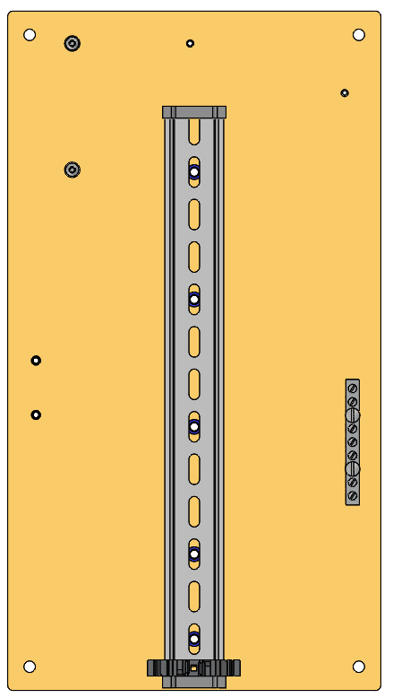
I'm designing an electrical panel backplate, in 5052 Al sheet metal. Around the centerline of the plate's long axis (about 16" x 8.5" outer dims.), it will have 5 x M6 holes positioned in a "straight line", for mounting a standard 35mm x 7mm EN50022 top hat profile din rail. It's a close clearance for M6 screws (depending on mfg., 6.3mm or 6.2mm width on the slots). I'd prefer not to use M5's if I can help it... it will carry some hefty components, and with 3xM6 screws, I'm seeing more movement than I'd like.

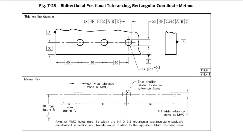
In this situation, I have a lot of tolerance for positioning errors of the overall hole pattern. I really don't care if the linear pattern ends up being positioned off of the centerline by 10mm (as an extreme example), or is rotated at an angle of 5 or 10 degrees from the centerline. I would like the hole pattern to be placed within 1mm of a top or bottom reference edge, though. As long as the holes are placed as close to co-linear as possible along an imaginary line (maybe +/-0.05mm max tolerance?), things should work out. Even the spacing from hole to hole can be off by a bit, since the slots give ~12mm of adjustment.
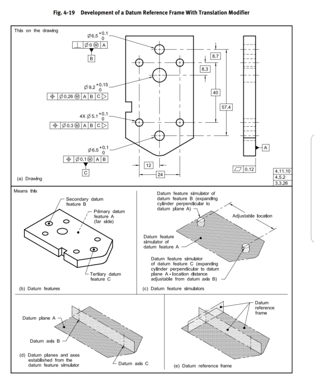
This particular part will be CNC laser cut, and will use PEM self clinching nuts to quickly fasten components to the sheet, so I think the hole position repeatability along the vertical axis of the part is going to end up well within the tolerances needed for screws to fit, regardless of how I specify the eng. drawing. I was mostly curious about how it would best be done using GD&T, since I'm still a beginner. I wasn't able to find a similar situation anywhere online.
Many Thanks,
Mike
I'm designing an electrical panel backplate, in 5052 Al sheet metal. Around the centerline of the plate's long axis (about 16" x 8.5" outer dims.), it will have 5 x M6 holes positioned in a "straight line", for mounting a standard 35mm x 7mm EN50022 top hat profile din rail. It's a close clearance for M6 screws (depending on mfg., 6.3mm or 6.2mm width on the slots). I'd prefer not to use M5's if I can help it... it will carry some hefty components, and with 3xM6 screws, I'm seeing more movement than I'd like.

In this situation, I have a lot of tolerance for positioning errors of the overall hole pattern. I really don't care if the linear pattern ends up being positioned off of the centerline by 10mm (as an extreme example), or is rotated at an angle of 5 or 10 degrees from the centerline. I would like the hole pattern to be placed within 1mm of a top or bottom reference edge, though. As long as the holes are placed as close to co-linear as possible along an imaginary line (maybe +/-0.05mm max tolerance?), things should work out. Even the spacing from hole to hole can be off by a bit, since the slots give ~12mm of adjustment.
This particular part will be CNC laser cut, and will use PEM self clinching nuts to quickly fasten components to the sheet, so I think the hole position repeatability along the vertical axis of the part is going to end up well within the tolerances needed for screws to fit, regardless of how I specify the eng. drawing. I was mostly curious about how it would best be done using GD&T, since I'm still a beginner. I wasn't able to find a similar situation anywhere online.
Many Thanks,
Mike


