Continue to Site

Eng-Tips is the largest engineering community on the Internet

Intelligent Work Forums for Engineering Professionals

  • Congratulations waross on being selected by the Eng-Tips community for having the most helpful posts in the forums last week. Way to Go!

GD&T Best Practices for DIN Rail Hole Patterns 1

Status
Not open for further replies.

Widget_Maker

Electrical
Dec 11, 2020
2
Hi All,

I'm designing an electrical panel backplate, in 5052 Al sheet metal. Around the centerline of the plate's long axis (about 16" x 8.5" outer dims.), it will have 5 x M6 holes positioned in a "straight line", for mounting a standard 35mm x 7mm EN50022 top hat profile din rail. It's a close clearance for M6 screws (depending on mfg., 6.3mm or 6.2mm width on the slots). I'd prefer not to use M5's if I can help it... it will carry some hefty components, and with 3xM6 screws, I'm seeing more movement than I'd like.
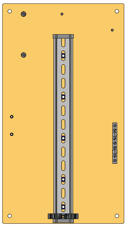
backplane_pic_b8zvr0.png


In this situation, I have a lot of tolerance for positioning errors of the overall hole pattern. I really don't care if the linear pattern ends up being positioned off of the centerline by 10mm (as an extreme example), or is rotated at an angle of 5 or 10 degrees from the centerline. I would like the hole pattern to be placed within 1mm of a top or bottom reference edge, though. As long as the holes are placed as close to co-linear as possible along an imaginary line (maybe +/-0.05mm max tolerance?), things should work out. Even the spacing from hole to hole can be off by a bit, since the slots give ~12mm of adjustment.

This particular part will be CNC laser cut, and will use PEM self clinching nuts to quickly fasten components to the sheet, so I think the hole position repeatability along the vertical axis of the part is going to end up well within the tolerances needed for screws to fit, regardless of how I specify the eng. drawing. I was mostly curious about how it would best be done using GD&T, since I'm still a beginner. I wasn't able to find a similar situation anywhere online.

Many Thanks,

Mike
 
Replies continue below

Recommended for you

I assume you are working according to ASME Y14.5, some version.
My suggestion:

1. Establish an initial DRF by designating the large face to which the holes should be perpendicular as datum feature A, the width of the plate (or one of its sides if you really don't care about the symmetry) as datum feature B, and the top or bottom edge as datum feature C.

2. Use that DRF by applying a relatively generous position tolerance on the first and the last holes of the pattern (the ones farthest away from each other) with reference to |A|B|C|. You will later see how this locates your entire pattern relative to the edges of the plate.

3. Designate the two abovementioned holes as datum features D and E.

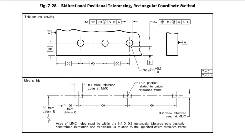
4. Position the 3 intermediate holes to the following datum reference frame: |A|D-E|, by using the Bidirectional Positional Tolerancing, Rectangular Coordinate Method (see image below from ASME Y14.5-2009), apply a generous tolerance in the longitudinal direction of the pattern (controlling the spacing between the holes) and a tight tolerance (possibly 0.1mm according to the +/-0.05mm you mentioned) In the right-left direction, controlling the alignment.
Screenshot_20201211-232343_Drive_d15gdg.jpg
 
Burunduk,

This was excellent, thanks so much for the guidance!

Our fabricators aren't picky with regards to the Y14.5 rev, so this works well (we're fortunate to work with a small-er sized shop).

Using those outer two holes to make the relative datum reference is a great approach. It positions things well, and even I (a newbie) can decode the design intent.

Many Thanks,

Mike

 
Glad to be of help, Mike.
Note that if the revision year of the Y14.5 standard is not an issue, you can base your drawing definitions on any revision you and the shop you work with have access to. In the latest revision, the relevant concepts are unchanged.
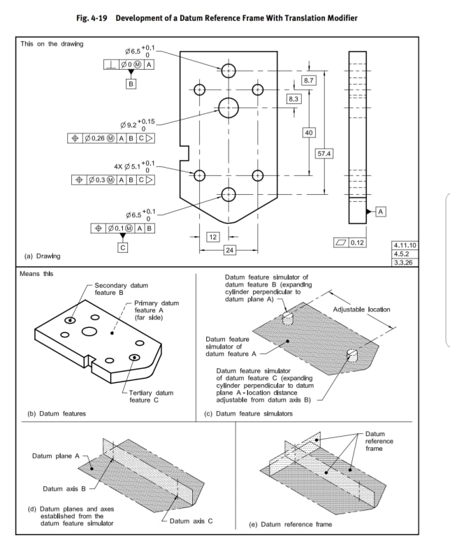
One thing I overlooked in my first response is that |A|B|D∆| (the triangle after D is supposed to represent a translation modifier, imagine it rotated 90° clockwise) is probably a better choice over |A|B-D|. My reasoning for the Multiple Datum features method (the B-D reference) was because the two outer holes have identical significance for datum reference frame establishment and there is no preference for one preceding the other in constraints of degrees of freedom. This also means that their datum feature simulators should be engaged simultaneously. If these were clearance holes, it would work fine. But for threaded holes, it is much less practical, and there is nothing wrong in making one hole constrain more degrees than the other (D would be the clocking datum in the |A|B|D∆| DRF, constraining only the last rotation). The translation modifier is there because the default requirement for any datum feature simulators that establish the same datum reference frame is to have a fixed relationship between each other according to the basic dimensions. This requirement is defined since the 2009 revision of the standard. Threaded gages will self-center in the holes and obviously, it would be very hard to attempt to maintain fixed basic spacing between them, and it's unnecessary. Below is a figure explaining how establishment of a datum reference frame works with a translation modifier. In your case, the role of the expanding pins will be taken by the thread gages used as datum feature simulators.

20201214_205525_amtq8j.jpg
 
Hi,

It looks to me that datum features D and E are not necessary. Why can't you position the hole pattern against A | B | C ? Datum feature B is center plane of the rail, and datum feature C is end of the rail.

Best regards,

Alex
 
Hi jassco,
The OP is asking about the threaded holes in the plate, not the clearance holes in the rail.

I suppose you could make a transition of your suggestion to the holes in the plate, but:
He also expressed that he wants to allow a loose positioning tolerance of the pattern relative to the edges of the plate and a much tighter tolerance that controls their alignment relative to each other (along a "straight line"). Controlling the pattern with a tight tolerance value relative to the edges of the plate will do the alignment job, but it will be too restrictive regarding the location of the entire pattern.

By the way, a composite position tolerance could also be an option, but I think it would be a bit cumbersome with the bidirectional tolerance method (the bidirectional method - because he wants a loose spacing control).
 
Hi, Burunduk:

I think this is a classical good example of pattern positioning. You position the slots on the rail to its A | B | C. Then you position the threaded holes on the plate to its A | B | C.

Tight tolerance between threaded holes can be controlled with position tolerance without datum.

Best regards,

Alex
 
Jassco,
On the plate, how do you suggest to combine the position with reference to |A|B|C| and the position without datum? Multiple Single-Segment/Composite tolerance? And how would you allow the different values of tolerance in different directions (for loose spacing + tight alignment)?
 
Hi, Burunduk:

Please see Fig. 7-28 you posted. Change positional tolerances to composite tolerances. Lower segment will show position without datum as a refinement. They control position of threaded holes to each other in the pattern. You can use two composite tolerance. One is for horizontal direction, and the other for vertical.

Best regards,

Alex
 
Jasso,
I agree it is also a possible solution.
However, note that the datumless refinement will not control the perpendicular orientation of the threaded holes to the face of the plate. If a composite tolerance solution is implemented, I would recommend referencing |A| in the second segment to avoid poorly controlled orientation.
However, using the two holes as datum features D and E may be simpler for the fabricator to digest if they are not very knowledgable at GD&T (small machine shop). Composite may appear complex, especially if combined with the Bidirectional method which alone may require some explaining to be made.
 
Status
Not open for further replies.

Part and Inventory Search

Sponsor