Brokenengineer
Mechanical
Hi all,
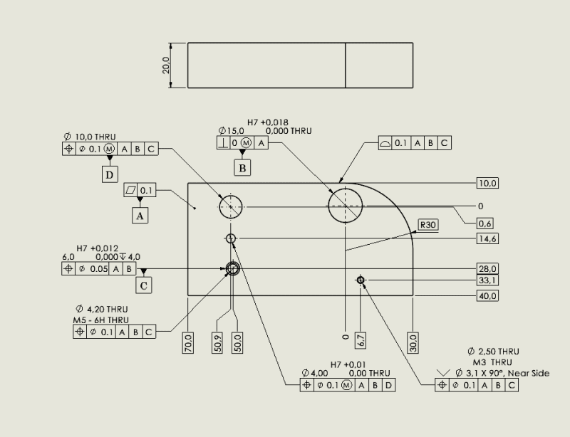
I was hoping if someone could review my use of Datums and FCFs in this example sketch. I am creating a production drawing for a part, and will be applying a GD&T scheme similar to this. But this is one of my first formal uses of GD&T,

To understand design intent: The 15mm hole aligns with the centre axis of a mating disc. The 6mm hole is used to align a detent to rotationally align the disc. The other features are items that interact at certain points on the disc.
My main questions are:
Is the use of datum A and B sufficient to position the Hole used for Datum C?
Can all other features then reference ABC as Datums?
Have I used the MMC correctly?
Is the outer profile FCF used correctly?
Please see attach image. Also I know the sketch is not drawn well, but I put this together in a rush.
Many thanks for your help! I am in in the process of booking a GD&T course with my company but this drawing needs to go out within a few weeks.
I was hoping if someone could review my use of Datums and FCFs in this example sketch. I am creating a production drawing for a part, and will be applying a GD&T scheme similar to this. But this is one of my first formal uses of GD&T,

To understand design intent: The 15mm hole aligns with the centre axis of a mating disc. The 6mm hole is used to align a detent to rotationally align the disc. The other features are items that interact at certain points on the disc.
My main questions are:
Is the use of datum A and B sufficient to position the Hole used for Datum C?
Can all other features then reference ABC as Datums?
Have I used the MMC correctly?
Is the outer profile FCF used correctly?
Please see attach image. Also I know the sketch is not drawn well, but I put this together in a rush.
Many thanks for your help! I am in in the process of booking a GD&T course with my company but this drawing needs to go out within a few weeks.
