Continue to Site

Eng-Tips is the largest engineering community on the Internet

Intelligent Work Forums for Engineering Professionals

  • Congratulations SSS148 on being selected by the Eng-Tips community for having the most helpful posts in the forums last week. Way to Go!

GD&T FOR HOLE DRILLED PERPENDICULAR TO DATUM

Status
Not open for further replies.

durablack2

Automotive
Jun 25, 2013
58
Capture_yszy0k.png


I used Solidworks Dimexpert to create the GD&T scheme you see in the picture.

In the feature control frame for the Ø7mm hole, why do datums A and C need to be called out at MMC? I don't understand how if datum A or Datum C increases, it will affect position of the hole, that is located about the centerline.

When looking at examples in Y14.5 I do not see any examples that show this same logic being used. All I see are datums being referenced with no modifiers.
 
Replies continue below

Recommended for you

First of all, you don't have to use an MMB modifier on datum features A or C.

So with your drawing, using them definitely increases the amount of locational error you can have, but not in the way you might think. It doesn't actually increase the 0.5 value that you have in your feature control frame, but it does allow that 0.5 tolerance zone to shift around depending on the sizes of A and C.


John Acosta, GDTP Senior Level
Manufacturing Engineering Tech
 
I should clarify, this is how SW Dimexpert automatically applied datum features and modifiers when assigning datums this way. But I was skeptical because I haven't seen any examples like this before.

So correct me if I'm wrong, the following should be true:

When looking at the hole
Case 1 - MMB modifier on C
The hole can be positioned off center by 0.25/2 + 0.5/2 = 0.375

Case 2 - No MMB modfier on C
The hole can be positioned off center by 0.5/2 = 0.25

Is this logic correct?

 
durablack2,

Applying MMC or LMC to a datum in the Feature Control Frame as you have shown is called MMB or LMB (Maximum/Least Material Boundary respectively) - this concept pops up all over Y14.5 and is introduced in sections 4.11.3 through 4.11.9 . Applying the MMB/LMB modifier on a datum allows you to take advantage of what is called datum shift. This is an often misunderstood topic which is sometimes confused for a bonus tolerance - datum shift/MMB/LMB NEVER provides additional bonus/positional tolerance, as powerhound stated it allows your tolerance zone(s) to shift around the datum. Its a small detail but an important distinction.

There are quite a bit of resources/forum posts out there on this topic but one recently that really helped me personally to solidify my understanding of datum shift and how it differs from a standard bonus tolerance was
 
durablack2,

chez311 offered a link to very good discussion about concequences of presence of MMB modifier in a feature control frame.

As for your calculations, they need to be adjusted, but before that, I would like to ask you following question:
What do you mean by: "The hole can be positioned off center by..."?

Do you want to know how far off of the true/perfect position (i.e. how far off of the datum C) the hole can be, or do you want to know how far off of the center plane of datum feature C the hole can be?

Although it may sound like it is the same, it is not. If you want to know the former, then the so called 'datum feature shift' or 'datum shift' has no impact because, as it was mentioned earlier by others, datum feature shift never increases size of position tolerance zone**. But if it is the latter, then the possible datum feature C shift will have to be added to the calculations because datum feature shift loosens relationship between toleranced feature (hole) and the datum feature.

--------
** To all -- I guess this is one of good reasons why explanation in terms of tolerance zone shift around the datum might cause a confusion. If the tolerance zone is allowed to shift around the datum, this would mean that the toleranced feature's axis or center plane or center point would be allowed to wander farther from the datum than just the distance equal to the half of the tolerance zone size.
 
pmarc -- your footnote is very important. It's true that datum shift doesn't cause the tolerance zone itself to get larger. But in a way, datum shift does allow us to "tolerate" more deviation.

So I don't get too freaked out when people say that datum shift creates extra tolerance. It does yield extra tolerance, but we just can't say that it's directly additive (with the rare case of coaxial features with a single datum reference). It just requires careful explanation.

John-Paul Belanger
Certified Sr. GD&T Professional
Geometric Learning Systems
 
J-P,
The point of my footnote wasn't just to say that datum shift doesn't cause the tolerance zone to get larger. Datum shift doesn't also cause the tolerance zone to shift relative to the datum(s).

As you well know, the entire datum shift concept can be explained in different ways. Some people shift part relative to gage (i.e. datums), some shift gage relative to part. I am fine with both interpretations, but there is one thing that doesn't/shouldn't change - it is that tolerance zones are always fixed relative to the datum(s). Otherwise the entire theory behind establishing true orientation and location of tolerance zones relative to datum reference frame falls apart.
 
Perhaps it is also possible to describe it in these words:
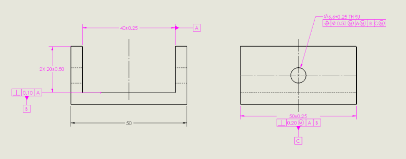
MMB modifier on a datum allows relative translation between the datum feature and the datum feature simulator. In case datum feature C in the drawing is produced smaller than 50.25, such translation is possible to the limit applied by the produced size.
Since the datum plane is derived from the datum feature simulator (fixed at MMB size) and not the datum feature (which might be smaller), then it is possible to say that for a given as-produced location of the hole relative to the faces of the datum feature, the MMB modifier allows some freedom to bring the hole "artificially" to the tolerance zone disposed about the datum plane. This of course doesn't change the location of the hole relative to the datum feature, but it may allow acceptance of parts that could be rejected if the datum was called out RMB, and thus the datum feature simulator was supposed to be kept adjacent to high points on the faces of the datum feature.
So I agree that in order to properly answer whether the calculation is correct, the "center" from the wording "off center" should be further defined, but my guess is that the center is the center of the RAME of datum feature C, so it is correct (edit: that is, if the calculation was done for a hole produced at MMC size, i.e. not including any bonus tolerance).

Another edit: durablack2, I recheked your the calculation, and as far as I can tell a hole produced at MMC can be offset from the center of the related actual mating envelope of datum feature C by as much as 0.5, not 0.375. That happens when the RAME size is 49.75.

semiond
 
If we assume that A has been referenced RMB in the positional callout for the hole, OP's calculations are not correct for Case 1 - MMB modifier on C, because the maximum possible datum feature C shift is 0.35 = (50.45-49.75)/2.

So if the hole has been produced at MMC size (6.35), it can be 0.6 (0.25+0.35) off of the center plane of the Related Actual Mating Envelope of datum feature C.

If the hole has been produced at LMC size (6.85), it can be 0.85 (0.25+0.25+0.35) off of the center plane of the Related Actual Mating Envelope of datum feature C.
 
pmarc,
You are right, I forgot to include the 0.2 perpendicularity tolerance to the calculation of the MMB size of datum feature C.
And as can be understood from your reply, since A is not referenced RMB, the condition of that feature also has impact.
So it's not that simple to provide any values.
 
pmarc said:
As you well know, the entire datum shift concept can be explained in different ways. Some people shift part relative to gage (i.e. datums), some shift gage relative to part. I am fine with both interpretations, but there is one thing that doesn't/shouldn't change - it is that tolerance zones are always fixed relative to the datum(s). Otherwise the entire theory behind establishing true orientation and location of tolerance zones relative to datum reference frame falls apart.

pmarc said:
Do you want to know how far off of the true/perfect position (i.e. how far off of the datum C) the hole can be, or do you want to know how far off of the center plane of datum feature C the hole can be?


Pmarc,
Would you mind if I am asking you for a little more details about those two interpretations. And No, I am not asking for scketches and schemes as I do know they are time consuming, but maybe some good book references where someone can get the details.
Or maybe even some more verbiage from you specially on “but there is one thing that doesn't/shouldn't change - it is that tolerance zones are always fixed relative to the datum(s). Otherwise the entire theory behind establishing true orientation and location of tolerance zones relative to datum reference frame falls apart”

This question :” Do you want to know how far off of the true/perfect position (i.e. how far off of the datum C) the hole can be, or do you want to know how far off of the center plane of datum feature C the hole can be?”
bother me for the last few days. And yes, I did loose sleep over it
 
greenimi,
What I basically meant by that is that the toleranced feature's axis or center plane or center point must fit inside its tolerance zone (cannot be farther from the datum(s)) in order to say that the part conforms to the drawing specification.
 
pmarc said:
To all -- I guess this is one of good reasons why explanation in terms of tolerance zone shift around the datum might cause a confusion. If the tolerance zone is allowed to shift around the datum, this would mean that the toleranced feature's axis or center plane or center point would be allowed to wander farther from the datum than just the distance equal to the half of the tolerance zone size.

I know this was directed at me and I'm fine with it. I am fully aware that the tolerance zone doesn't actually move, but this is the way that I've found successful to explain how datum feature shift allows more locational tolerance without it actually being bonus tolerance, dependent on the size of the feature being controlled. Once that concept is grasped, then I'll refine it with something like "Now imagine instead of the tolerance zone moving, it's actually locked in place and the part itself can move as much as the fixture will let it." Saying things like "...a shift on the datums" or any other GD&T specific terminology that most people in a fundamentals class wouldn't understand just serves to muddy the water even more, in my opinion. It works for me when I'm there for the follow up. Maybe it's not such a good idea to explain it here when I can't always come back with the follow up.

John Acosta, GDTP Senior Level
Manufacturing Engineering Tech
 
Should I understand that datum shift is a misnomer? There is no such of “animal”. There is only a datum feature shift.

In fig 4-18 the 4 holes (Ø7.7-8.1) tolerance zones can be a different sizes (depending on the size of the RAME), but their location is always perfect to the datums A, B and C.
Also, the tolerance zones are not allowed to shift around the datums established from the datum feature simulators.

I still have trouble imagining how “sitting on a part” method is explained and the coordinate system is moved.
Maybe “sitting on the gage” and the part is moved/rotated fits my brain a little bit better.
 
pmarc and John,
I've seen your post only after I submitted mine. But anyway, could you please explain to the fundamental level how the datum feature shift works when explained to the students? I am not a teacher in any way, shape or form, but I know that if I want to become one (not sure when either) I have to understand it myself to the greatest level of details. Einstein said: “If you can't explain it to a six year old, you don't understand it yourself.” So, I am working on my own understanding.

Thank you for your help
 
Status
Not open for further replies.

Part and Inventory Search

Sponsor