Continue to Site

Eng-Tips is the largest engineering community on the Internet

Intelligent Work Forums for Engineering Professionals

  • Congratulations KootK on being selected by the Eng-Tips community for having the most helpful posts in the forums last week. Way to Go!

GD&T for Threaded holes 6

Status
Not open for further replies.

Inund8_ca

Mechanical
Sep 23, 2022
9
Hi all,
My coworkers and I can not agree on the proper GD&T for this situation:
We have a shaft, with an offset blind hole in it. There are 2 threaded holes which run perpendicular to the hole. I need the GD&T to indicate that the set screw holes need to go through the thickest section of the part, otherwise the screws used here will fail in various ways.
Due to the constraints of the design, we cannot change the thread pitch of the screw holes.

This is what I have proposed, but I also feel at the same time that it's overkill. I'm also unsure if my perpendicularity callout on the threaded holes makes sense, since it references a derived median line datum, and a feature of size datum that is parallel to first.
And one colleague takes issue with the datum scheme, saying that the shaft should be the primary or secondary datum.
I'm curious to hear what solutions come to mind.
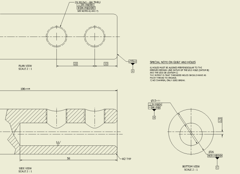
Screenshot_2023-06-15_084805_hweure.png
 
Replies continue below

Recommended for you

I would place myself as not qualified to answer your question, but maybe my answer could help someone more qualified see what I'm seeing and cut thru the print...

The upper thread perpendicular callout is referencing two competing datum axis B and C. If those axis are not perfect to each other how can you define perpendicularity? Then you have both threads positioned to ABC so they need to be drilled/threaded within 0.15 parallelism to A which competes with the upper callout perpendicularity.

I'm not sure how you get a callout to achieve the 'thickest area for the setscrews' without some type of clocking feature.
 
The most sensible callouts seems to use the outer diameter as a datum feature (perhaps [A]), tolerance the location of the hole with a position tolerance and identify the hole as a datum feature (perhaps ), tolerance the set screw holes using the outer diameter and the hole as a common datum ([A-B]). Not sure about the end surface; how it is located, but it might be a perpendicularity or profile tolerance to a datum, probably [A} as specified here, and perhaps some other surface. The end surface would then be identified as a datum feature (perhaps [C}) so the set screw holes could reference it as well as in [A-B|C].
 
Since position also controls orientation, what was the logic that led to applying both position (which works on the pattern of two threaded holes) and perpendicularity (which works only on each hole separately) with the same value, and with a different primary datum feature?

Consider of how this part assembles and what is the functional purpose of the threaded holes and ask yourself:

1. Do you need both position and perpendicularity? If not, get red of the perpendicularity requirement.

2. What is the functional primary datum feature, i.e. what feature will orient the part when assembled in two rotational degrees of freedom? Is it datum feature A or B or maybe C or two of them together such as maybe B-C, or something else?

3. If both perp. and pos. are needed, consider whether a smaller value for perp. with reference to the same primary datum feature used in the pos. feature control frame is what you actually need.
 
sendithard: I hadn't thought of clocking this... I will give it some thought.

Burunduk: Thinking back, I believe my logic was that there was no explicit callout or dimension restricting where the threaded holes should lie.

The truth of this is that the position of the holes on the length of the shaft is not important, but passing through the thickest part of the shaft is. Shouldn't a perpendicularity callout referencing 2 parallel datums result in that? Meaning I wouldn't need the position tolerance?
EDIT: To be honest, I think I put them both there because I wasn't sure if the perpendicularity was enought

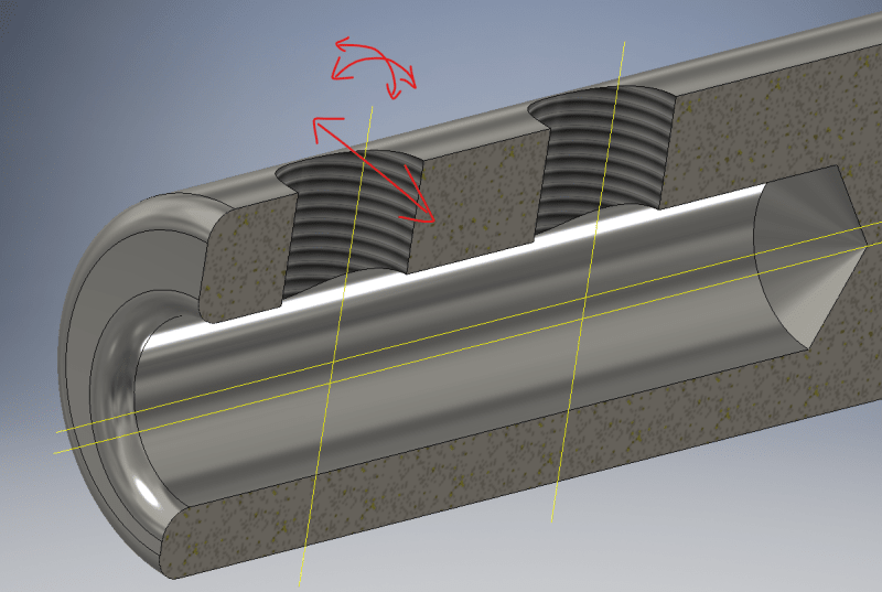
Only the degrees of freedom in red need to be controlled by GD&T. Since the perpendicularity calls out both the hole and the OD, shouldn't it all those DOF's be controlled?
Screenshot_2023-06-16_111009-_qerpdp.png
 
Side-to-side variation is not controlled by perpendicularity. Rotation about an axis is not controlled by perpendicularity. If a plane defined by a compound datum is where the feature axis lies, that orientation is also not controlled by perpendicularity -> use angularity or parallelism.

If you don't care where the holes are along the part, remove the dimensions that appear to located them.
 
Perpendicularity is an orientation control and as such, it won't constrain a translational degree of freedom. You want the holes to be drilled at the center of the shaft, that's why you need location, and that's achieved by position. If the axial location is much less important, you can use a bidirectional tolerance of position.
 
Inund8_ca, where did you learn about GD&T?
 
One more thing - using two offset cylindrical features (the non-coaxial OD and hole) in the same control does achieve clocking.
 
Thanks, Burunduk for supporting my initial reply. I'm giving you a star.

Edit - Sorry - I can't give every single reply you made a star. They are all great.
 
@Burunduk Since clocking is achieved, I suppose all that's needed is the datums and the location tolerance.

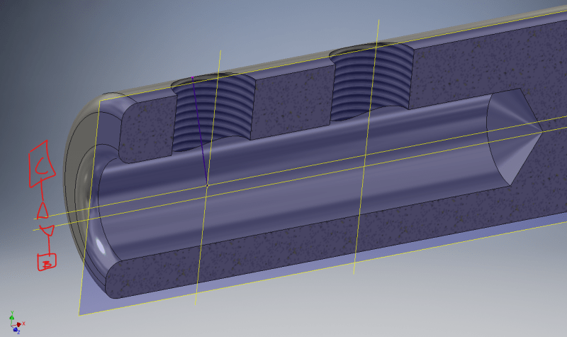
@3DDave My logic was this: If you have 2 parallel axes, how can it create a line that passes through both with restricting its position to the plane of symmetry? Sorry if that doesn't make sense or is mentioned in y14.5. Illustration below, purple line showing a line which COULD be perpendicular to both, but not simultaneously, or at least not with a single circular hole. If the hole axis doesn't pass through both axes, wouldn't that result in a smaller tolerance zone, decreasing with the sine of the angle away from the central plane?
I learned GD&T in college a while back and have been trying to relearn by reading through my old textbooks and gdandtbasics.com. I don't have a copy of y14.5 and have not read it.


Screenshot_2023-06-16_142921-_hoygaq.png
 
Screenshot_2023-06-15_084805_hweure_update_z7mjdw.png


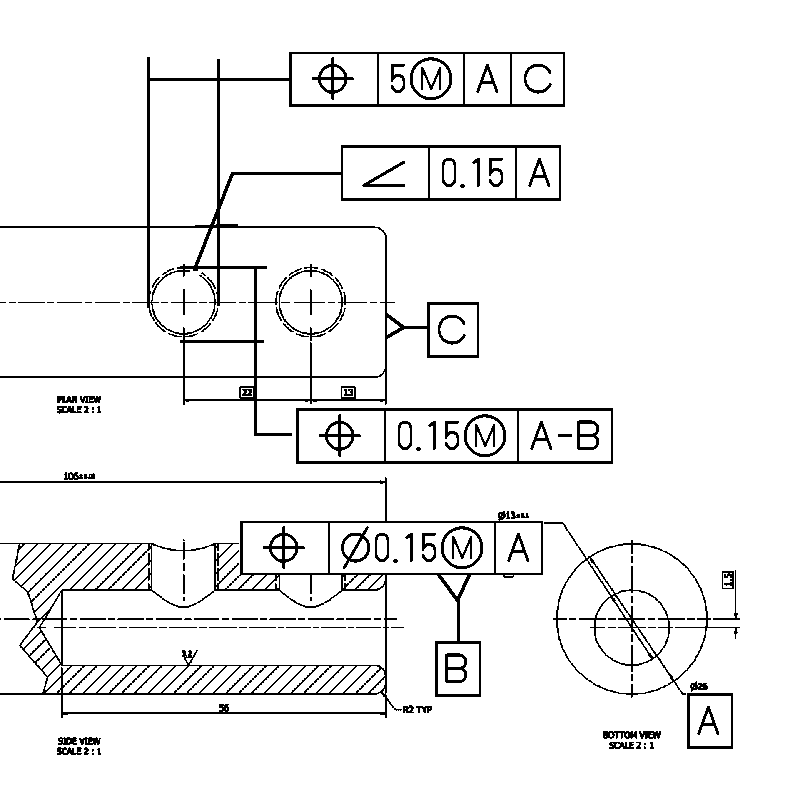
I would add the 2X hole thread and other sizes and whatever datum feature C is controlled by but my patience with GIMP has completely run dry and am tired of fighting to get it to draw what I want it to draw.
 
Inund8_ca said:
Since clocking is achieved, I suppose all that's needed is the datums and the location tolerance
Possibly. Generally the location tolerance or tolerances (position, potentially bidirectional as you were suggested) will also control the orientation within the specified values. But if you want to tighten the tolerance for orientation, consider angularity, as suggested by 3DDave above. Note in his figure, that just like for the bidirectional position tolerances, the angularity value is not preceded by a diameter symbol. This means that the axis is limited by a tolerance zone of two parallel planes perpendicular to datum axis A - which does make sense, since clocking is controlled by position to A-B, not by the orientation tolerance.

3DDave, you get a star for this one.
 
3DDave said:
I would add the 2X hole thread and other sizes and whatever datum feature C is controlled by but my patience with GIMP has completely run dry and am tired of fighting to get it to draw what I want it to draw.

GIMP is like that. Thank you for your effort.
 
This seemingly simple part is actually a good GD&T head scratcher!

I wouldn't use the two "parallel" axes of the part as a datum because they may not be parallel. They would "fight" with each other.

If the machine shop has a multi-axis machine they could make it with one setup and everything would pretty much be dead-nuts on. The problem may come about when trying to inspect it. If the shop has a Faro/Romer Arm it shouldn't be much of an issue so long as they have a probe tip that can reach down into the blind hole a good ways.

If the shop doesn't have a multi-axis CNC machine nor an inspection arm that is where the difficulty will begin.

If it's the latter situation here's what I would do:

[ul]
[li][/li] If you could add two fairly wide-surfaced opposing flats, sort of like wrench flats, somewhere along the OD of the part (preferably at the end) that would be easier to use as a clocking datum. I say wide surfaced because the wider the surface, the more accurate your clocking will be. So the dimension from flat-to-flat would need to be as small as you can tolerate.
[/ul]

[ul]
[li][/li] This wrench flat clocking datum would be referenced at RFS. You could use this datum for both positioning the offset blind hole and the setscrew holes.
[/ul]

[ul]
[li][/li] If these wrench flats are not acceptable the only practical way that I know of for you to accurately clock this part in the real world is to think of it as something like a camshaft. Because you're dealing with curved surfaces and not flat perpendicular edges it's really hard to know exactly where the center will be. In the world of engine building there is a process of Degreeing-In the camshaft. Even though the cam and crankshaft have keys which are clocking features, professional engine builders want to know for sure where that cam is installed at as far as degrees in relation to the crankshaft is concerned. The way they do this is by screwing in a hard stop into the spark plug hole of the #1 cylinder. Then they install a degree wheel onto the front of the crankshaft. They rotate the engine forward until the #1 piston hits the hard stop and set the degree wheel to zero. Then they rotate the engine backward until the #1 cylinder hits the hard stop again and put another mark on the wheel. Then they divide those degrees in half to determine exactly where Top Dead Center is on the #1 cylinder. Then they rotate the crank to this halfway mark. Then they reset the degree wheel so that the pointer is now pointing at zero on the degree wheel. Now that they know where Top Dead Center is they can use an indicator to start checking the valve lift figures against the camshaft spec sheet and advance the cam as required. It would be helpful to watch a YouTube video to understand the process.
[/ul]

[ul]
[li][/li] So if you're using the method above, the only way I know of for checking for "Top Dead Center" or TDC on this part would be to chuck the part in a four-jaw chuck and adjust it till the center blind hole runs true with zero runout (what a pain). Then use a dial indicator along the OD and the Finding TDC Routine to know exactly when you're at the thickest upper part of the shaft.
[/ul]

[ul]
[li][/li] I wouldn't use perpendicular, parallelism, or angularity to control the orientation of the setscrew holes. They're just setscrews. It's not going to make or break the functionality of the assembly if they're minutely tilted. What's more of a concern is that they might loosen so just use some threadlocker. Just use position because position does also control perpendicularity.
[/ul]

[ul]
[li][/li] The other thing to note is that you have the position of the threads at MMC. It might be easier check the threaded holes at RFS. Also, it might be easier to add the note MINOR DIA below the thread position Feature Control Frame so that they can just check the ID of the threaded holes rather than the actual pitch diameter of the threads.
[/ul]

Hope this helps.
 
Eric Gushiken said:
It might be easier check the threaded holes at RFS.

I would be careful here... almost nothing is easier to inspect at RFS. But I do agree with your follow-up statement that the minor diameter would make it easier.
 
I've never used them but there are threaded hole inspection gages which have slits in them and are flexible. This makes it easy to engage the threads at RFS. It would be harder to check threads at MMC because there would be slop between your inspection tool and the threads and it would be impossible to truly know how much clearance you really have.
 
Hi Eric,
There's been a lot of good discussion about that topic on this forum -- the pros and cons of MMC on threads. Here's a search for the keywords MMC on threads; it's interesting to see the different nuances:

[URL unfurl="true"]https://www.eng-tips.com/search.cfm?pid=1103&action=Search&q=mmc+on+threads&t=&h=&searchSite=1&searchArea=1&d=1&s=1[/url]


John-Paul Belanger
Certified Sr. GD&T Professional
Geometric Learning Systems
 
Lots of interesting new discussion here!

Eric Gushiken said:
They're just setscrews

inund8_ca said:
I need the GD&T to indicate that the set screw holes need to go through the thickest section of the part, otherwise the screws used here will fail in various ways.
Due to the constraints of the design, we cannot change the thread pitch of the screw holes.

The hole purpose of the GD&T is to control the set screws location and form. Due to size constraints, the wall here only has about 4-5 threads along the center plane after being counter-sunk. And yes, they are not using CNC mills, just a CNC lathe and a series of jigs. Using a single jig would be far more effective imo, but I haven't made contact with them personally, so I don't know how well my suggestion would be received. Choosing a supplier is above my pay grade as well, so no shot there.

EDIT: My understanding was that RFS is typically harder to measure manually as well. Could you dive a bit into that?
 
Inund8_ca -- you can look through the threads that my search link yields for the deep dive, but the short answer is that RFS can be difficult because it requires a physical gage to expand/contract so that we find the center of that feature "regardless of feature size." On the other hand, MMC/MMB is easier because a physical gage can be made at a single size (MMC/MMB).
The curveball with threads is that we don't feel any bonus or jiggle; the thread is engaged until it's finger-tight (or reaches a designated torque). But threads still have tolerance, so "M" on a thread is possible.

John-Paul Belanger
Certified Sr. GD&T Professional
Geometric Learning Systems
 
Status
Not open for further replies.

Part and Inventory Search

Sponsor