Geordil
Mechanical
- Jul 25, 2018
- 19
Continuing this from the other thread so as not to hijack.
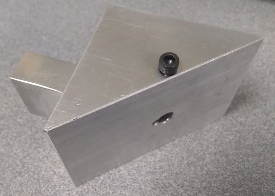
Here is what I have so far, after making some adjustments based on advice already received.
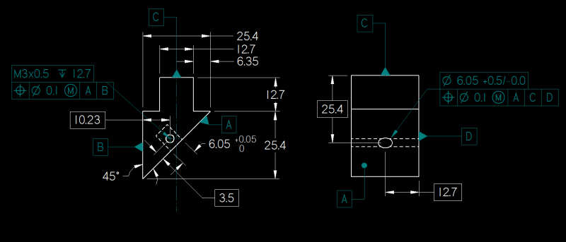
Thanks to all in advance.
Here is what I have so far, after making some adjustments based on advice already received.
Thanks to all in advance.