Eng-Tips is the largest engineering community on the Internet

Intelligent Work Forums for Engineering Professionals

  • Congratulations waross on being selected by the Eng-Tips community for having the most helpful posts in the forums last week. Way to Go!

GD&T position Mutiple segment - Calculating min and max span of bolt holes.

Status
Not open for further replies.

Radius1

Mechanical
Jan 13, 2021
37
US
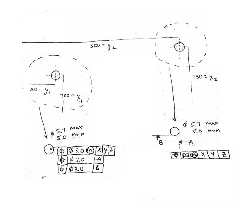
Two holes, diameter min = 5.0 , max = 5.7
Hole 1 coordinates 700 =x1 , 200 = y1
Hole 2 coordinates 750 =x2, 500=y2

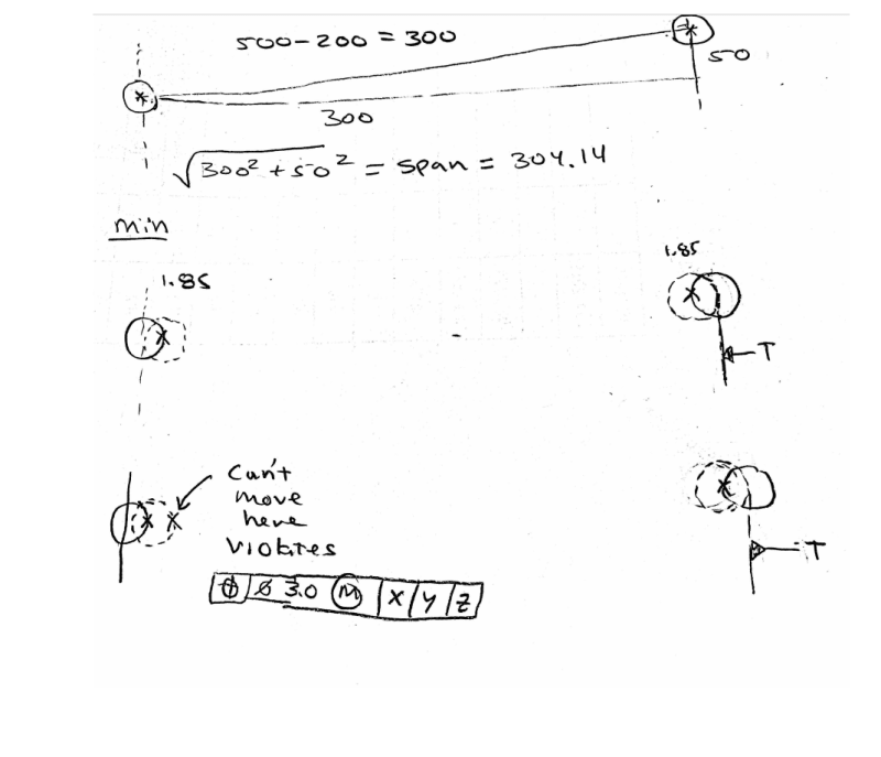
I am struggling how to find the min span of the holes with the given multiple segment position tolerance. The span will be the hypotenuse of the triangle formed by the holes. So the trig is easy, it's finding the min y, and x under the constraints of the positional tolerances that is challenging.
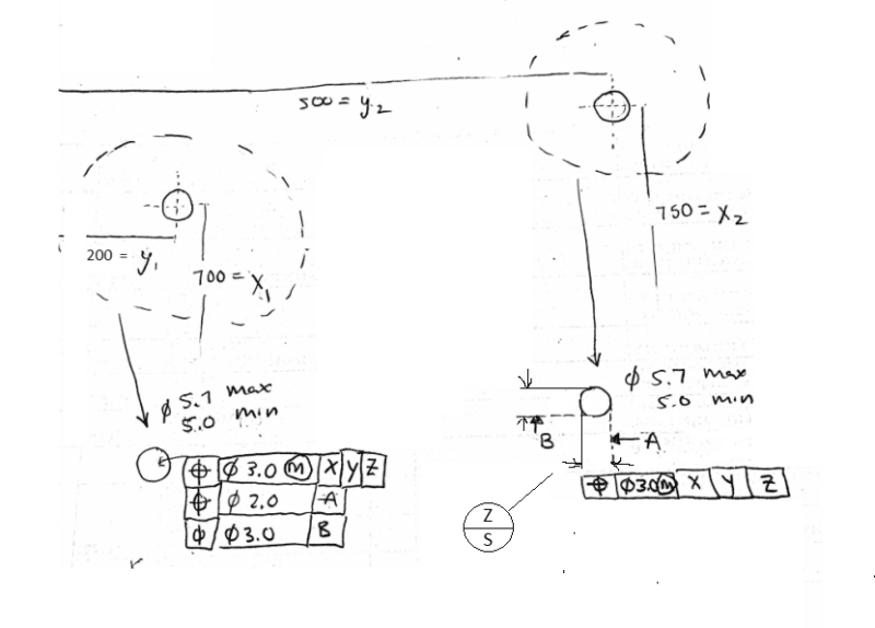
Muti_position_Holes_aijudc.png
 
Replies continue below

Recommended for you

here is my attempt at calculating.

The nominal is easy, it is simply the hypotenuse as shown.

Where I am having trouble is with the min case. Taking the largest holes, diameter of 5.7 , so that 5.7 -5.0 = 0.7 which is a bonus tolerance of 3.7/2 =1.85

So then hole 1 , shifted over 1.85 to the right from nominal, similarly and hole 2 shifted to the left 1.85. Now with the 2.0mm tolerance from datum T, does this mean that hole one can only move back to the left, 1.0mm and not towards the right, because it would violate the 3.0mm xyx, global positional tolerance?

Muti_position_Holes_2_flivuu.png
 
Once you find the hypotenuse, it's identical to any other 1-dimensional calculation.
The GD&T is given with diameter symbols, so the tolerance is the same in all directions. The "min span" cannot be spoken of in terms of left or right, because now your stack-up is sitting on a diagonal.

John-Paul Belanger
Certified Sr. GD&T Professional
Geometric Learning Systems
 
Hi Belanger,
this is where I am having trouble. The adjacent leg of the tringle will change from nominal and be at min, at 3.0 positional tolerance when hole 1, is 1.5 to the right, and hole 2, is 1.5 to the

left. This creates a smaller adjacent section, which then results in a smaller hypotenuse.

so then wouldn't the hypotenuse change as well, because span is a function of the y and x distances?
 
Help me clarify your question... Do you want to find the max/min span directly between the holes? Or the max/min distance in the individual x and y directions relative to the datums?

John-Paul Belanger
Certified Sr. GD&T Professional
Geometric Learning Systems
 
The span directly between the holes. min / max

And how to understand 2.0 mm position relative to datum A. I believe this call out refines , the 3.0 mm position tolerance, meaning restriction.
 
The position tolerance doesn't get applied to the X and Y dimensions. It gets applied to each hole from its singular, perfect location.
Also, it's confusing to talk about X and Y directions and also have the datum features be X, Y, Z. (Maybe I need to see a fuller view where all the datum features are identified -- I don't understand what datum T is supposed to be, or how it plays into the position callouts.)

Anyhow, the perfect span between them would be the 304.14 that you calculated (that's the basic distance, also known as the Theoretically Exact Dimension).
Then, around that perfect span, each hole's axis is allowed a position tolerance of diameter 3 mm at MMC. To find the worst-case, imagine each hole made at its biggest size of 5.7 mm. You've already done that in your post above, and that means that the position tolerance for each hole could grow to 3.7 or, 1.85 radially.
Thus, the maximum span would be 304.14 + (1.85)*2 = 307.84 mm (edited*)
And the minimum span would be 304.14 - (1.85)*2 = 300.44 mm (edited*)

(* = edited because I originally forgot that there are 2 holes involved.)

You asked about the perpendicular idea, relative to datum A. But that only affects one hole. To find the span between them, we have to examine the holes in the same datum reference frame, which would be X, Y, Z.

John-Paul Belanger
Certified Sr. GD&T Professional
Geometric Learning Systems
 
^I think there's 1 little mistake and that's that the maximum span would be 304.14 + 3.7 = 307.84 (since both holes can be a distance of 1.85 away from their ideal location). Same goes for the minimum span which would be 300.44. This is only taking the tolerance w.r.t. datums X, Y, Z into account. The tolerance w.r.t. datums A and B might decrease this tolerance.

Something else that's strange in the drawing is that A and B are not planes but seem to be the side of a hole. It's very weird to tolerance like that. Why not make the center of the hole datum A and tolerance in vertical and horizontal direction to the center of datum A? The tolerances w.r.t. datum A and B also have a diameter symbol which is incorrect since the tolerance zone is not a circle.

Edit: just calculated it. The tolerance w.r.t. datum A and B will limit the min and max span.
Max span is 305.37395 (= SQRT(301^2 + 51.5^2))
Min span is 302.90799 (= SQRT(299^2 + 48.5^2))

Edit 2: Just realized that the above calculation (Edit 1) is if datum A and B would be w.r.t. the center of the hole and not the sides. It's not correct to tolerance w.r.t. the sides of the hole but theoretically if you did the size tolerance also needs to be taken into account and the min and max span would be different.
 
Yikes -- Steven, thanks for pointing out my goof. That's what I get for firing off an answer in the late evening before a holiday weekend. [smile]
I've edited that post to show the correct answer.

As far as the datums go, we await the OP's reply about what the datum features are, and if the original question is center-to-center max/min or edge-to-edge max/min.
The side of a hole wouldn't be a datum (unless using datum targets, perhaps creating some sort of tangent plane).

John-Paul Belanger
Certified Sr. GD&T Professional
Geometric Learning Systems
 
References to datums A and B in this example are not interpretable as there is a non-basic dimension in the tolerance loop.

In general, asking the distance between centers, et al, based on tolerances on boundaries is nonsense used as a distracting teaching exercise. The distance between centers is fixed and the boundaries are fixed. That's the point of using tolerances that establish boundaries.

It is also another example of how poorly communicated these concepts are in the standards - especially about using the tangents to holes as datum features but not dimensioning from them.

It's also yet another reminder that there should be software that generates valid geometry in accordance with the stated tolerances so that users can see the effects, particularly of degenerate or pathological acceptable solutions. Get users to apply form tolerances in the millionths of an inch just to be sure.
 
Hi Belanger,
After looking at the drawing closer, This looks to be a target datum. (Z/S)

But without the ability to share the actual print, this seems to be adding more confusion, as my hand copy is missing key items. (Sorry)

Z_plane_kgzvkh.png


I'll see if I can find a better open-source example. Which I have searched before and have never seen the datums on the edge of the holes. However, in my daily work, I have encountered this practice with multiple companies.
 
If you have encountered this from many companies and are in Michigan, it's possible you are working with tier 2 and tier 3 companies to one auto manufacturer and that company is the only source of that weird "edge of hole" application.

Because [A} and are referred to separately they don't have to be measured perpendicularly to each other.

What is your reason to determine the minimum span?
 
3DDave, I was asked to compute the min span, in order to create a gage for making sure parts fit.
 
If you're interested in parts fitting together, then most likely you would want to find the "virtual condition," which is a simplified formula to create simple functional gages for position (and a few other GD&T callouts) when the MMC modifier is involved. Would you like help in using that method?
Either way, the datum features called out are still strange :)

John-Paul Belanger
Certified Sr. GD&T Professional
Geometric Learning Systems
 
So you don't know why.

The gage for the first component has two fixed diameter pins and the datum feature simulators for X, Y, and Z located at the basic offsets and of the smallest diameter minus the position tolerance - 5.0 - 3 = 2 mm diameter. If it fits and the holes meet the diameter requirements the part passes.

I would be very concerned if the primary datum feature for the first segment is not nominally perpendicular to the holes.

There is no reasonable way to gauge the second and third segments.

Make up a distance and ask the person who told you to do this if it is right - make them do the work. If they say go with that made-up number, then don't worry. The request is unreasonable and whether it rejects usable parts or accepts unusable parts, it won't be long before the disaster on the assembly line triggers an actual investigation into what the requirement should have been.
 
Hi Belanger,
Yes, I would very much like to see the virtual condition calculations for this particular application. Provided it is not too much trouble. I'll give it a try as well.
 
Virtual condition is the fancy name for the constant-size worst-case boundary for the hole, accounting for its size (smallest) and its position error happening at the same time. 3DDave actually presented it above: 5.0 - 3.0 = 2.0
In GD&T textbooks, the general formula is written as: MMC size - the stated position tolerance = VC

Thus, you could construct a gage with two pins of exactly 2.0 diameter, spaced at the exact basic dimensions from the datums (in this case, X, Y, Z).
There might be a side discussion about the accuracy of the gage (even gages have tolerance), but now you at least know how to calculate "virtual condition."

John-Paul Belanger
Certified Sr. GD&T Professional
Geometric Learning Systems
 
Status
Not open for further replies.

Part and Inventory Search

Sponsor

Back
Top