Eng-Tips is the largest engineering community on the Internet

Intelligent Work Forums for Engineering Professionals

GD&T - Position of bore relative to stock bar hex 1

Status
Not open for further replies.

James Baker

Mechanical
May 24, 2024
2
0
0
GB
Hi all,

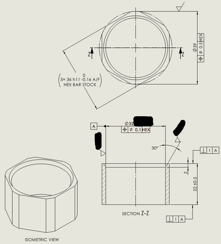
I have a simple part which has a machined bore which must have its position controlled relative to the external hex of the bar stock (if viewing it from the machinist's perspective). We've been having trouble discussing this internally and have tried multiple different approaches, none of which we're satisfied with. I've attached a screenshot of the drawing as it stands (with several unimportant redactions).

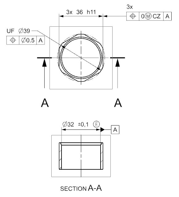
I've seen numerous forum posts of hex features being controlled relative to a diameter using profile on the hex, but that can't apply here as the hex isn't machined, so has its own stock tolerance, and the position of the bore must be tighter than the stock A/F tolerance on the hex. On the drawing I've indicated what I want to achieve, functionally, via the position tolerances with the hex as the datum (I understand this is not OK!), but if there's a suitable solution where the bore is the datum and the position of the hex is controlled regardless of size, that is also fine in my eyes.

Any guidance on how best to detail this will be greatly appreciated!

NB I'm aware that the h11 tolerance on the hex is strange, but that's how the supplier (Parker steels) tolerances it!

Many thanks,
James
 
 https://files.engineering.com/getfile.aspx?folder=d1a9163c-1a09-4d72-ab14-2fec29e182ae&file=Hex_Bar_Stock_Bore_Position_Problem.jpg
Replies continue below

Recommended for you

James said:
if there's a suitable solution where the bore is the datum and the position of the hex is controlled regardless of size, that is also fine in my eyes.

Sounds like something that could be handled using the dynamic profile modifier, 'Δ,' after the profile tolerance value. Which standard and year of issue are you using for dimensioning and tolerancing?
 
Nothing strange in h11 on bar stock becasue cold extrusion is a fairly precise forming process. Round bars usually come in h8 stock tolerance so h11 is no big deal either.
 
There are three pairs of opposing flats, so make each pair a datum feature and then create three position tolerance feature control frames for each of the features, one to each of the datum features; this will not use a diametral tolerance.

This will best center the round feature axes to each of the three pairs of flats, Regardless of Feature Size (RFS), even if the widths differ and even if the angles are not precisely 60/120 degrees apart. It will also match how this could be aligned in a lathe.

It may also required to use CF (continuous feature) symbol on the outer diameter position tolerances.

Hex_Bar_Stock_Bore_Position_Problem_u8442e.jpg
 
Many thanks to you all for the replies thus far!

In response:

CheckerHater said:
As you already use DIA 32 as the datum feature A, do you think you can reverse your position requirements?
- Yes, more than happy to; I just want whatever GD&T is clearest to indicate the position requirement without adding in any nasty inspection.

Burunduk said:
Which standard and year of issue are you using for dimensioning and tolerancing?
- We use the plethora of BS ISO standards, so BS EN ISO 1101:2017 is what applies here (I believe). You're correct in saying that the modifiers in this case would be CZ or UF, as per this excerpt:
The tolerance requirement applies to each surface or line element independently, unless otherwise
specified, e.g. by using a CZ symbol to combine the tolerance zones or by using the UF modifier to
indicate that the compound feature shall be considered as one feature.
However, this is where the standards really start to do my head in, as UF is only really mentioned for use on continuous features, so I find it ambiguous whether it can be applied to the six faces only on a hex with corner breaks... CZ is shown for use on discontinuous faces in the standard so that's probably my preference at this moment in time! Iain Macleod Associates Ltd posted an article in 2011 saying that ISO/TC 213 will be reviewing whether seperate UF and CZ modifiers are even necessary; that's too deep a rabbit hole for me to spend the time finding out if they've discussed it.

Wuzhee said:
Nothing strange in h11 on bar stock becasue cold extrusion is a fairly precise forming process.
- The reason I thought it was strange wasn't because of magnitude of the tolerance band, but more because I've never seen parallel faces with BS EN ISO 286-2 tolerances applied; interesting though, as I've just re-read the scope and found this!
For simplicity, and also because of the importance of cylindrical workpieces of circular section, only these are referred to explicitly. It should be clearly understood, however, that the tolerances and deviations given in this part of ISO 286 equally apply to workpieces of other than circular sections. In particular, the term “hole” or “shaft” is used to designate features of the cylinder type (e.g. for the tolerancing of the diameter of a hole or shaft) and, for simplicity, these terms are also used for two parallel opposite surfaces (e.g. for the tolerancing of the thickness of a key or the width of a slot).

3DDave said:
There are three pairs of opposing flats, so make each pair a datum feature and then create three position tolerance feature control frames for each of the features, one to each of the datum features; this will not use a diametral tolerance.
- We like this, and it feels intuitive to interpret. Thanks a lot for the detailed explanation!

James
 
I will assume that BS EN ISO 1101:2017 has the same definitions as ISO 1101:2017.

James Baker said:
UF is only really mentioned for use on continuous features, so I find it ambiguous whether it can be applied to the six faces only on a hex with corner breaks...

According to ISO 1101:2017, 3.9:
"united feature
compound integral feature which may or may not be continuous, considered as a single feature"

On another thread here, I recently posted this example, figure 48 from ISO 1101:2017.
If that tolerance was applied to a group of flat surfaces, cylindricity would not be applicable, and I believe the specification that would be the closest to convey a similar intent would be a surface profile tolerance with the UF modifier above the tolerance indicator and OZ modifier after the tolerance value inside the indicator. The OZ modifier, for a closed shape, neutralizes the size control, and for a datumless profile, it would only control the form. Adding datum references and keeping OZ would also put location and orienration under control (still without limiting the size). That would be the ISO equivalent of ASME's dynamic profile modifier, 'Δ,' which I mentioned earlier. You could apply it to control the hex relative to the bore.
 
Hi James,

I would keep datum "A" as the center line of the bore and tolerance the the outer diameter as UF Ø39 with a position tolerance with respect to "A". I have not done this my self, but for a hex I have seen the following approach being used; 3x 36 h11 with a position tolerance at MMC and reciprocity requirement.

Something similar to the attached figure. I can´t seem to find the correct circled "R" in my version of NX, so it shows the equivalent Zero tolerance at MMC instead.
You need CZ to evaluate the 3 mid planes together with fixed TED angles within the group.

Sk%C3%A4rmbild_2024-05-24_195755_fevoa0.jpg


Edit; I was a bit quick with my first reply.. Since You are starting out from a HEX bar and want to locate the hole as precise to the hex as possible I am considering 3Ddaves approach to be practical. A common datum derived from the flats of the hex, and reference the hole to that common datum.
 
rimag said:
A common datum derived from the flats of the hex, and reference the hole to that common datum.

I think that to establish a common datum there would need to be TED of the 120° angles defining the hex;

BS EN ISO 5459:2011 said:
Intrinsic characteristics introduced by the collection of features (defining the relation between the associated features) shall by default be considered theoretically exact for both linear and angular dimensions.

Since the hex is a stock feature defining TED for the intrinsic characteristics (and requiring corresponding tolerances for them) may be considered problematic.
 
Status
Not open for further replies.
Back
Top