Eng-Tips is the largest engineering community on the Internet

Intelligent Work Forums for Engineering Professionals

  • Congratulations waross on being selected by the Tek-Tips community for having the most helpful posts in the forums last week. Way to Go!

GD&T scheme to control amount of twist in rectangular prismatic shapes?

Status
Not open for further replies.

mmolt

Mechanical
Jul 13, 2004
37
0
0
US
Hello all, I'm hoping you can help me determine a reasonable strategy to control the amount of allowable twist in a rectangular prismatic shape?

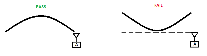
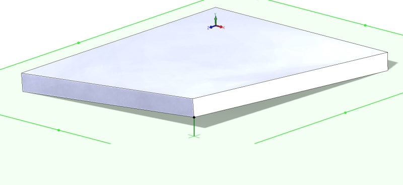
If you look at the following picture, I sometimes deal with the types of parts that can have twist induced by various means of manufacturing. This is the type of twist that can be recognized by putting the part on a granite slab, and noticing one corner of the part will rise up from the slab when it's opposite diagonal corner is pushed down to contact the slab. In fact, it's quite practical for us to measure this twist by inserting feeler gauges into the gap between the slab and the rising corner. So we have a reasonable way to check and measure this condition, I'm just looking for advice on datum placement and feature control designation. Perhaps parallelism?

twisted_rect_prism_pvvgdd.jpg
 
Replies continue below

Recommended for you

First would be flatness on what ever face is going to be your datum. Then you could use parallelism on the opposite face if needed. Flatness alone may be enough if the thickness is well controlled.

----------------------------------------

The Help for this program was created in Windows Help format, which depends on a feature that isn't included in this version of Windows.
 
Thanks for your reply dgallup. My first thought was flatness as well, and maybe I'm thinking about this wrong, but recognizing and checking for flatness in it's most idealistic definition might get parts rejected that wouldn't be a problem.

For instance, let's say I call out a flatness of .08". Imagine the part itself isn't twisted whatsoever, but the middle of the surface has a gradual .09" dip in it...by using flatness, it would be rejected, when in fact that isn't a condition I intend to reject.
 
There's no symbol to control "rocking."

You could define four tiny areas, one at each corner of the face, and impose a profile tolerance, ignoring the rest of the part.
 
You could define four tiny areas, one at each corner of the face, and impose a profile tolerance, ignoring the rest of the part.

This was sort of along the lines of what I was thinking - initially I was considering a non-uniform datumless profile tolerance to provide margin at some region towards the middle of the part, though noting that might be a little strange since it would be non-uniform in 3 dimensions. I think I like your solution better.
 
Thank you guys! I was thinking I was missing something simple, but it's starting to sound like this issue is somewhat unique. ...and I realize GD&T wasn't intended to cover all geometry conditions simply.

I'm wondering if it just makes sense for me to define some sort of work instruction or critical to quality document that I'll refer to on the drawings that define how to measure this condition, with the quantifiable amount to check for listed on each drawing.
 
Depending upon the design intent of the part, Flatness of the Derived Median Plane could be an option. If your design intent can handle using mmc bonus tolerance then you can use a gage to check the part.
 
Flatness of the Derived Median Plane could be an option

OP seems to want to reject a feature based not just on magnitude of deviation, but also shape. For a simplified example of what I believe this to mean see the below:

PLANAR_TWIST_afqriw.png


A note about 3DDave's suggestion - it would need a datum feature reference of the side of interest, essentially making it self referencing. Otherwise the 4x small zones can be shifted any way necessary to make the feature fall within tolerance, unless there is gross, pure twist with one of the corners significantly out of plane (ie: both convex and concave bowing would pass though). I know the OP references twist but I assumed this to also mean any kind of twisting/bowing which effectively results in "rocking". Such a reference would require either the tolerance zone to be twice as large (as the self reference means half the tolerance zone would be unusable) or unilateral with the entire tolerance zone shifted to the usable side. This could be avoided with my initial suggestion of a non-uniform tolerance zone though (as I said, unsure how to properly notate this in 3D - perhaps with a model?).
 
Also thinking up creative solutions - perhaps one could specify a special requirement along the lines that the angular difference between any two valid candidate datum planes of a given candidate datum set may not exceed a certain value. This would essentially limit the amount of rocking.
 
Based on what 3DDave mentioned...this is sorta where I arrived...I do however feel like I'm butchering the surface profile definition by attempting to restrict it to a measurement point. Is there a better way of doing this?
example_kfz1ph.jpg
 
mmolt,

I do not believe the application of a profile tolerance to a single point(s) would be valid. Additionally, you have datum feature A referenced as both a planar feature as well as consisting of datum target points A1-A3, it is not clear which you are referring to. My personal opinion would be that your datum feature A should consist only of the fully planar feature as shown by the side view and the single datum feature symbol, otherwise please refer to my response (21 Oct 19 12:38) use of datum target points will accomplish nothing that a datumless profile won't do (reject only twist with a single out of plane point - fully convex error/rocking will not be rejected) besides halving the tolerance zone.

I believe the below utilization of indicating an area over which a profile tolerance applies would be valid, as long as it has a basic location/size denoted.

4--1_f97ofm.jpg


Note also per my response (21 Oct 19 12:38) if you do this method which includes self referencing datum feature(s) a standard uniform bilateral tolerance will only have half the tolerance zone available. Since this only applies to one side of the feature, the solution would be to either double the allowable tolerance or change it to a unilateral (unequally disposed) profile tolerance which has all the tolerance available inside the material. See below from Y14.5-2018 for examples - this is of course assuming you are utilizing Y14.5, even if using past versions (ie: 2009 or earlier) this was the generally accepted interpretation, however it is now for the first time included in the body of the standard with 2018.

11-21_gtc9cw.jpg


11-22_yjxcdn.jpg
 
chez,

Per all the documentation I've consulted, identifying the datum (A), and more specifically the 3 datum targets (A1, A2, & A3) that define datum (A) is perfectly legitimate.
Also see here: Link

If the profile tolerance was OK to use for a point, it would suit my needs perfectly for defining the allowable twist of this part.

Anyone else have any suggestions? I'm again wondering if using GD&T is more trouble than it's worth in this instance...particularly when notes and instruction could convey the needs - perhaps more clearly.
 
mmolt,

Respectfully I would recommend consulting the primary documentation - ie: the standard itself. Y14.5-2009 and 2018 share a figure very similar to the one in your link but without the mixed symbology. I would consider such mixing improper without specific clarification as to how the datum feature is to be evaluated (ie: planar feature vs. datum target(s)) - which I think would be cumbersome and would be better served with different notation. At the very least I would consider such mixing of symbols bad practice and to be avoided - unless you don't care how your inspectors interpret such an open ended specification.

2009_vs_2018_nqso57.png


To add to this fact, datum targets will not result in the behavior you are looking for - it will not reject all of the different variations of parts which result in the same amount of "rocking". A fully convex (or in the 3D world - imagine a "cupped" or dome shape) feature which will rock significantly on a surface plate - which I think you would want to reject based on your previous statements - will pass. See below for a simplified example in 2D.

pass_fail_-_convex_lh5wlh.png


I stand by my statement that I do not believe profile of a point is a valid concept. You are welcome to attempt to implement it, but I do not believe that it is supported by the standard. I'm not clear as to why you don't think a profile tolerance applied to an area will not suit your needs - it can be as small or as large as you see fit and is not problematic unlike attempting profile of a point.

mmolt said:
I'm again wondering if using GD&T is more trouble than it's worth in this instance...particularly when notes and instruction could convey the needs - perhaps more clearly.

That all being said, the added complexity of the above specification may not be required. A simple note stating something along the lines of "when laid on a surface plate against datum feature A, a shim no larger than 'X' may be inserted at any point along the edge of the part" may be sufficient for your requirements. For what its worth, such a statement would be closer to the specification I recommended with use of a planar datum feature and NOT datum targets, seeing as a surface plate is a planar datum feature simulator.
 
I would like to amend my previous post. Apologies for not catching this but apparently Y14.5-2009 fig 4-53 shows the practice you describe, apparently the committee in their infinite wisdom did not pick up on this until 2018 - this same figure has since been changed to notate datum feature A and B along with their respective accompanying datum targets A1,2,3 and B1,2,3. See the below highlighted.

I still stand by my statement that without the below shown notation per Y14.5-2018 fig 7-64 it would be bad practice to mix the datum feature and datum target symbols with the same letter designation, despite its inclusion in 2009.

7-64_f1x0fg.jpg
 
chez,

I appreciate the response. I've found multiple sources (textbook and online tutorials) that suggest utilization of (3) datum targets to define a single datum is an acceptable practice. One of these textbooks is used to teach all aspects of technical drawing to engineering students. This methodology seems to be suggested for surfaces that include variation not critical to part performance...which is also my case.

Perhaps you can you point me to a source that explicitly states utilization of (3) datum targets to define a single datum plane is not allowed?

Again, I'm trying to catch twisted parts, NOT rocking parts due to a domed shape or otherwise. Rectangular prism shapes can rock, yet not be dome shaped. This is why I've avoided simply calling out the surface as a datum, if I did, we will end up rejecting parts (parts with concave or convex domes) that would otherwise function just fine.

The engineering work instructions I've referenced on the print snippet above describes methodology to measure and check for the twist condition...so there won't be confusion by inspection.

I'm attempting to do two things on the print:
1. Define the twist acceptability requirements in the most technically appropriate way (GD&T, etc.).
2. Refer to a reasonable way to check for twist, which is covered by the work instructions listed.

(1.) seems to be more trouble than it's worth???
 
chez,

I'll amend my comments about the datum reference as well, and prefer the datum methodology A1,2,3[A] you've shown.
 
Yes, that's what I'm saying, since apparently there are individuals who may have issues with applying profile tolerance to points. And I wouldn't refer to A in that profile callout.
 
Status
Not open for further replies.
Back
Top