Eng-Tips is the largest engineering community on the Internet

Intelligent Work Forums for Engineering Professionals

GD&T Tolerance

Status
Not open for further replies.

nedders

Mechanical
Feb 15, 2023
13
0
0
GB
Hi

I haven't used Geometric tolerances for a while, so I just wanted to double check I'm not going insane

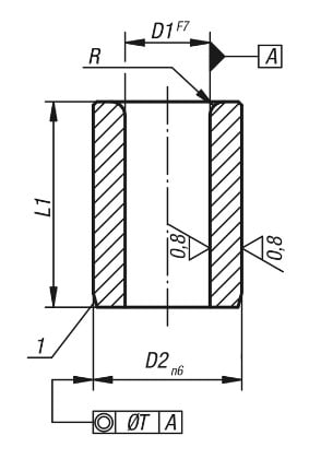
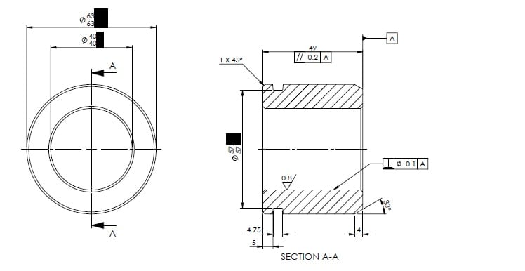
I stumbled across a drawing (see attached / or below post), and I'm pretty sure the geometric tolerancing is wrong.

1) The parallelism looks to be on a wrong face?

2) Also, personally I would have thought it would have been better to datum A the external of cylinder and put a concentricity on the internal, rather than a perpendicular?

Thanks
tolerances_nfgiyc.jpg
 
Replies continue below

Recommended for you

(re-posted from the original entry) I see no problem with where the 'A' datum has been established nor the use of the parallelism constraint. True, it would seem that there is a missing concentricity constraint, perhaps even two, as the bottom of the groove needs to be constrained as well, plus the walls should be parallel to the 'A' datum as well, but then we have to assume that there are default tolerances, in which case, the only tolerances needed on the drawing are those which are either more or less precise than what the defaults standards would indicate.

John R. Baker, P.E. (ret)
Irvine, CA
Siemens PLM:

The secret of life is not finding someone to live with
It's finding someone you can't live without
 
Thanks John, In reference to the parallelism, if the datum is the flat (top / underside, rather than side), then the 49mm dimension is actually perpendicular to this, not parallel.
This was my understanding of it.
I thought the parallelism would be on a face parallel to this, but i may be wrong
 
The parallelism constraint should be anchored or pointing to the surface to which it applies. The dimension is actually perpendicular to the constrained surface.

"Know the rules well, so you can break them effectively."
-Dalai Lama XIV
 
Yes, I missed that, although that does not change the fact that the 'A' datum itself appears to be appropriate.

John R. Baker, P.E. (ret)
Irvine, CA
Siemens PLM:

The secret of life is not finding someone to live with
It's finding someone you can't live without
 
nedders,

Is this ASME Y14.5 or ISO?

I can interpret the drawing. The primary datum feature is the face to the right. The bore is required to be perpendicular to it. This is a standard way to apply controls to round parts. The application of the parallel tolerance is weird to me and possiby wrong. My interpretation of it is that the 49mm face is to be parallel to datum feature[ ]A.

At this point, your drawing is missing controls. If the 40mm[ ]ID is datum feature[ ]B, you can apply a positional tolerance to the 63mm[ ]OD and the 57mm[ ]groove, or specify run-out.

You select datum features based on requirement. My assumptions above are that you locate the flat face and then the ID. Note how the inside face has a surface finish specification, albeit, not a particularly smooth one.

--
JHG
 
You also select datum features based on being able to use them both when fixturing the stock in the machine tool(s) and when inspecting the final part during the QA process.

John R. Baker, P.E. (ret)
Irvine, CA
Siemens PLM:

The secret of life is not finding someone to live with
It's finding someone you can't live without
 
When the feature control frame of an orientation tolerance such as parallelism is attached to the size dimension of a feature of size such as the width of 49 mm, it means that the tolerance zone controls the center plane of that width. Which is odd, because datum feature A which the control uses is one side of that same width, and it indicates that this was probably not the intent.
 
Thanks for all your replies.

Note, this is not my original drawing, but one I came across, and you have confirmed my suspicions.

 
Another sample drawing for which no function is specified so no tolerancing can be properly determined. All that is clear is there aren't enough controls to exclude unusable parts. Maybe it's a semi-precision paperweight.
 
I believe it's a bush which has a pin to fit inside of it
The groove is for an o-ring to sit.

If it was me, I would have made the id and od with a concentric tolerance, and put the parallel on the 57mm face
 
Status
Not open for further replies.
Back
Top