dgallup said:
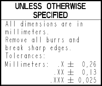
If you are doing metric dimensions then you can not use the number of decimal places to imply default tolerances in ISO. Trailing zeros are not displayed.
Yes, you cannot use the number of decimal places to imply default tolerances in ISO.
I guess I have to dust off my old post:
The ways to specify general tolerances without resorting to number of decimal digits:
1. Referring to ISO 2768:
“UNTOLERANCED DIMENSIONS PER ISO 2768 –mK-E”
Note: ISO 2768 may have different flavors around the world:
• Brazil: NBR ISO 2768
• England: BS EN 22768:1993 (ISO 2768:1989)
• France: NF EN 22768:1993 (ISO 2768:1989)
• Germany: DIN ISO 2768
• India: IS.2102 (ISO 2768)
• Italy: UNI ISO 2768
• Japan: JIS B 0405 (ISO 2768)
• Russia: GOST 308931-2002 (ISO 2768:1989)
• Sweden: SS ISO 2768
Don't worry, ISO 2768 will outlive it's "well-wishers"
")
2. Referring to (discontinued) ANSI B4.3-1978:
“UNLESS OTHERWISE SPECIFIED, GENERAL TOLERANCES PER ANSI B4.3 MEDIUM SERIES APPLY”
3. Referring to International Tolerance Grade
“UNLESS OTHERWISE SPECIFIED, ALL UNTOLERANCED DIMENSIONS ARE +/- IT14/2”
4. Referring to International Tolerance Grade (“extended” version):
“UNLESS OTHERWISE SPECIFIED, ALL UNTOLERANCED DIMENSIONS ARE:
HOLES H12, SHAFTS h12, OTHERS +/- IT14/2”
5. Tabulating:
Recreating in part or in whole Table 1 and/or 2 from ANSI B4.3-1978, or equivalent
6. Using single tolerance for all dimensions:
“UNLESS OTHERWISE SPECIFIED, ALL UNTOLERANCED DIMENSIONS ARE +/- 0.8”
(This is recommended for small parts with most of the dimensions falling within short range from each other)
7. Using industry-specific standards:
• ISO 8062 – tolerances and allowances for casting: “GENERAL TOLERANCES ISO 8062 – CT12”
• ISO 13920 – general tolerances for weldments: “GENERAL TOLERANCES ISO 13920 – BE”
8. Using country-specific standards:
• DIN 16901 (or newer DIN 16742) – German standard(s) for plastic part general tolerances
• NF T58-000 – French standard for plastic part general tolerances
• NF E02-352 – French standard for sheet metal part general tolerances
• JIS B 0410 – Japanese standard for sheet metal part general tolerances
The list can unfold virtually indefinitely, but it should be clear that users of metric standards are doing perfectly well without using “trailing zeros”
"For every expert there is an equal and opposite expert"
Arthur C. Clarke Profiles of the future