Continue to Site

Eng-Tips is the largest engineering community on the Internet

Intelligent Work Forums for Engineering Professionals

  • Congratulations KootK on being selected by the Eng-Tips community for having the most helpful posts in the forums last week. Way to Go!

General Tolerances Unless Otherwise Stated (Linear/angular) 1

Status
Not open for further replies.

Finglas

Mechanical
Jan 24, 2009
137
Looking for a standard which will help me define what we should be putting down on our SolidWorks drawing template when it comes to general Linear and angular tolerances.
Currently as follows in mm:
X: +/-0.25
.X +/-0.1
.XX +/-0.05
.XXX +/-0.010

Which standard should I be looking at in terms of ISO standards?
 
Replies continue below

Recommended for you

rothers said:
We use ISO 2768 parts 1 & 2


My advice: do not use ISO 2768!. Period.
There are mutiple problems with this standard and is going to be replaced very soon.

 
If you are doing metric dimensions then you can not use the number of decimal places to imply default tolerances in ISO. Trailing zeros are not displayed. I know lots of companies do this but that doesn't make it right. I hate ISO 2768, why should my tolerance change if my dimension 5.9 changes to 6.1? We use ONE default linear tolerance on all our drawings. KISS.

----------------------------------------

The Help for this program was created in Windows Help format, which depends on a feature that isn't included in this version of Windows.
 
dgallup said:
If you are doing metric dimensions then you can not use the number of decimal places to imply default tolerances in ISO. Trailing zeros are not displayed.

Yes, you cannot use the number of decimal places to imply default tolerances in ISO.

I guess I have to dust off my old post:

The ways to specify general tolerances without resorting to number of decimal digits:
1. Referring to ISO 2768:
“UNTOLERANCED DIMENSIONS PER ISO 2768 –mK-E”

Note: ISO 2768 may have different flavors around the world:
• Brazil: NBR ISO 2768
• England: BS EN 22768:1993 (ISO 2768:1989)
• France: NF EN 22768:1993 (ISO 2768:1989)
• Germany: DIN ISO 2768
• India: IS.2102 (ISO 2768)
• Italy: UNI ISO 2768
• Japan: JIS B 0405 (ISO 2768)
• Russia: GOST 308931-2002 (ISO 2768:1989)
• Sweden: SS ISO 2768

Don't worry, ISO 2768 will outlive it's "well-wishers" :)

2. Referring to (discontinued) ANSI B4.3-1978:
“UNLESS OTHERWISE SPECIFIED, GENERAL TOLERANCES PER ANSI B4.3 MEDIUM SERIES APPLY”

3. Referring to International Tolerance Grade
“UNLESS OTHERWISE SPECIFIED, ALL UNTOLERANCED DIMENSIONS ARE +/- IT14/2”

4. Referring to International Tolerance Grade (“extended” version):
“UNLESS OTHERWISE SPECIFIED, ALL UNTOLERANCED DIMENSIONS ARE:
HOLES H12, SHAFTS h12, OTHERS +/- IT14/2”

5. Tabulating:
Recreating in part or in whole Table 1 and/or 2 from ANSI B4.3-1978, or equivalent

6. Using single tolerance for all dimensions:
“UNLESS OTHERWISE SPECIFIED, ALL UNTOLERANCED DIMENSIONS ARE +/- 0.8”
(This is recommended for small parts with most of the dimensions falling within short range from each other)

7. Using industry-specific standards:
• ISO 8062 – tolerances and allowances for casting: “GENERAL TOLERANCES ISO 8062 – CT12”
• ISO 13920 – general tolerances for weldments: “GENERAL TOLERANCES ISO 13920 – BE”

8. Using country-specific standards:
• DIN 16901 (or newer DIN 16742) – German standard(s) for plastic part general tolerances
• NF T58-000 – French standard for plastic part general tolerances
• NF E02-352 – French standard for sheet metal part general tolerances
• JIS B 0410 – Japanese standard for sheet metal part general tolerances

The list can unfold virtually indefinitely, but it should be clear that users of metric standards are doing perfectly well without using “trailing zeros”

"For every expert there is an equal and opposite expert"
Arthur C. Clarke Profiles of the future

 
It totally makes sense for general tolerances to change with the size of the dimension. In general, large dimensions for large items are usually designed with larger clearances or allowances for deviation. A 1500mm wide machine base plate usually has no reason to be toleranced the same as a 5mm thick spacer plate. The larger the part, the more expensive it is to machine to a tighter accuracy. When designing machines, ISO standard tolerances are a decent compromise in general between accuracy and expense. If you are specifically considering the impact of the tolerance on your 5.9mm vs 6.1mm dimensions, you should probably add an explicit tolerance anyway.

 
Finglas,

Why are you using ISO standards on an inch drawing?

--
JHG
 
Thanks for all the feedback. It is a metric drawing template.
Arguments for each of the responses particularly as to why you would have a difference between 5.9 and 6.1 but as handleman pointed out, you should probably add an explicit tolerance anyway.

We're really just trying to find the most appropriate standard to use for defining general linear and angular tolerances (in metric format).
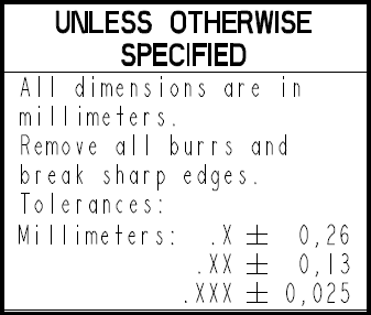
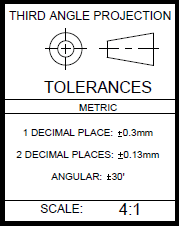
Below are some general tolerances on some of our customers drawings.
General_Tolerances_1_gbnx1a.png

General_Tolerances_2_yuu6pi.png

General_Tolerances_3_qotwbi.png

General_Tolerances_4_sj4akn.png
 
Finglas, if you have a copy of the ASME Y14.5 standard, read the paragraph for millimeter dimensioning. In the 2009 edition, see paragraph 1.6.1(c) and in the 2018 edition see paragraph 4.3.1(c).
Unlike inches (which are explained in the subsequent paragraph), when using millimeters it is forbidden to have any extra zeros after the last digit to the right. The drawing cannot display values of 12.00 or 12.000.
Thus, when using millimeters you cannot have a title block tolerance method which relies on the number of decimal places (unless, I suppose, you ensure that every dimension ends in an artificially induced digit that isn't zero).
So the general tolerance tables from your customers would not be proper (except the DIN 1688).

I know this rule was already mentioned by dgallup and CheckerHater. Your examples illustrate how common this practice is in industry.

John-Paul Belanger
Certified Sr. GD&T Professional
Geometric Learning Systems
 
I would love to see the meeting notes that said "Let's make the interpretation between inches and millimeters different in this one aspect that is arbitrary. Show of hands?"
 
Just to add - title block tolerances are a general hazard and the angular one(s) are almost universally ignored, to the extent that an entire military vehicle mod-kit, about 200-300 drawings worth, had no angular tolerances specified beyond, possibly, the rare explicit addition. Considering that a simple rectangular block has 12 angle dimensions to verify, and the project did not use FCFs beyond holes, the 500 to 2,000 (estimated) implied right angles went unremarked and un-inspected with the default of zero allowable tolerance.


I am amused by the mixing of the "." and "," notation in the last example image.
 
Finglas,

You can add this sticker (or at least idea of it) to your collection:

GENERAL_TOLERANCES_pgb00w.png


"For every expert there is an equal and opposite expert"
Arthur C. Clarke Profiles of the future
 
CheckerHater,

Speaking about ISO specification and applicable standards, I have a question for you:
Which ISO standards would YOU recommend having shown on an ISO defined drawing?
(8015, 14405-1, 1101, 5458, 5459, others, all of them:)?

Thank you
Andras


Andera,

ISO has what's known as "Invocation principle" which reads:

Once a portion of the ISO GPS system is invoked in a mechanical engineering product documentation, the
entire ISO GPS system is invoked, unless otherwise indicated on the documentation, e.g. by reference to a
relevant document.


So, essentially, specifying the entire group of standards is optional.

Nevertheless the following may be recommended:

ISO 1101 as fundamental standard.

ISO 14405 (with appropriate modifiers) to specify how you measure your sizes

ISO 8015 for fundamental principles

ISO 2768 (with appropriate modifiers) or alternative for general tolerances

Also don't forget:

View projection method

Dimensional units (if operating from US or Liberia)

Workpiece edges treatment

Surface texture

"For every expert there is an equal and opposite expert"
Arthur C. Clarke Profiles of the future
 
We have a very detailed standard that calls out every ISO standard that we use and any exceptions or stipulations. We call out our standard in every title block. ISO seems unworkable any other way, there are a lot of bat shit stupid ISO standards.

----------------------------------------

The Help for this program was created in Windows Help format, which depends on a feature that isn't included in this version of Windows.
 
Finglas,
Ideally, your company would want to avoid any general tolerance blocks and standards.

On your parts, tolerances on important features should be applied directly by toleranced size dimensions or feature control frames (I think the ISO terminology might be "tolerance frames"); for features of size, directly toleranced size dimensions are appropriate (but not the only option). For angular variation control, geometrical tolerances of orientation are appropriate.

Less important features can be controlled for variation by a general profile of a surface tolerance with a relatively generous value, specified in the drawing notes.
 
Status
Not open for further replies.

Part and Inventory Search

Sponsor