Eng-Tips is the largest engineering community on the Internet

Intelligent Work Forums for Engineering Professionals

Geroler Motor Speed Control

Status
Not open for further replies.

JIC-8

Marine/Ocean
Jul 27, 2024
4
0
0
CA
Hello,
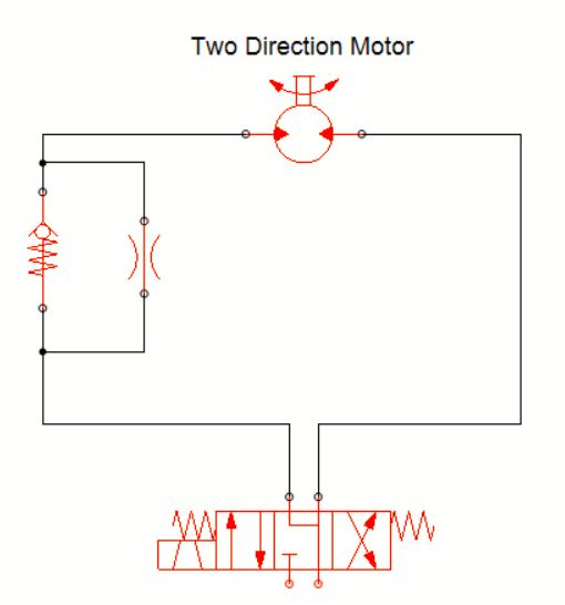
I am new to the forum and relatively new to hydraulics. I have a system consisting of 5 bi-directional geroler motors and 2 cylinders operated by open centre solenoid controlled directional control valves and supplied by a diesel driven gear pump. I need to slow down just one of the motors. Operating pressure in the motor circuit is very low - about 300 psi. The motor operates continuously and, ideally, I'd like to reduce the speed in only one direction of rotation. I have been following some posts regarding the control of cylinder ram speed with flow control valves but understand that controlling motors is different. I am unclear as to the effect of placing a uni-directional flow control valve (adjustable in one direction, free flow in reverse)in the motor circuit. Any advice would be much appreciated.
 
Replies continue below

Recommended for you

You need a directional flow control valve in one leg of the motor. Free flow in one direction, controlled flow in the other direction. Check valve with an orifice will do the job.

cxcx_xuz4it.jpg


Turn the check valve over if you want to meter the flow out of the motor.

The orifice is not pressure compensated, so there will be additional losses and heat to consider. If you want to avoid high losses, go for a compensated flow control valve.
 
I notice in the discussions on ram speed that there are pros and cons for meter in / meter out. Concerns over a runaway load don't apply here so would meter in be the preferred choice or does it matter?
 
Rotating systems have a tendency to overrun. The inertia of rotating mass can sometimes be an issue and the motor needs to be able to pull oil in, otherwise it will cause cavitation at the inlet port.

Linear systems can have the same problem, but they tend to have more friction than rotating systems that have roller bearings in.

Stopping the motor quickly can be an issue too.

The system drawn above will try to pull oil from the tank during overrun, but the orifice will be too restrictive. It would be the same on the other side too.

Also, metering output flow is additive to the load on the motor.

You’d have to give more details of the application to allow a more accurate solution.
 
If the motors have internal drain, it's not a good idea to put the orifice on the outlet side because that will pressurize the shaft seal.

When you have a fixed displacement pump (like your gear pump), you use a 3-port flow control valve instead of a 2-port, it will require less power because it doesn't pressurize the entire system.

Example of 3-port valves:
 
Fixed displacement pump may not play nice with an attempt to slow something down via flow controls. Right now the speed of the motor will be determined by the fixed displacement and speed (and thus flow rate) delivered by the pump, and the pressure will be determined by the back pressure due to whatever output torque the motor is delivering (plus flow-resistance losses). If you add restriction, the pump is still going to try to deliver its fixed displacement and it will spike its delivery pressure until something gives - hopefully the system relief valve. That's going to make it run hot.

Multiple functions on a system supplied by a fixed-displacement pump, some of which have open-centre valves, is interesting, too. If they're in the open-centre position, what happens to the flow? Is it all bypassing to tank through the open-centre valve? Does anything else move? Are the open-centre functions in series?

We need the schematic of the whole system, not just the one function ...
 
BrianPetersen, I agree with what you say. However, the type of 3-port flow control valves that I linked to exists for one reason and one reason only, and that is to slow down functions that run on fixed pumps. Doing the calculations for flow and pressure will tell you if significant heat is added, in that case you're better off with a variable pump.
A classical example is a sand/salt spreader mounted on a small tractor for pathways etc. The rotating axle at the bottom of the spreader runs pretty slowly to feed out the sand and requires fairly low pressure and the speed is typically regulated with a 3-port flow controller. Because it's a 3-port flow controller it bypasses flow instead of just restricting it and the pump doesn't see more pressure than the load. Yes these systems have losses but in low pressure applications the heat generated is usually well within what's acceptable.


JIC-8, when you say Open Center valve I assume you mean an Open Center mobile valve, like a Parker VO-40 or a Prince SV or a Walvoil SD5 or something like that? Not open center in the meaning A and B to tank in neutral?
 
Yes, if you use the type of valve that you linked, and not the type shown in the diagram a couple posts above!

we ... need ... the ... schematic ... for ... the ... whole ... system ... ! ! !
 
To be clear, the "system" drawn above is the most basic form and probably not appropriate as the system is restrictive and would simply generate heat and hardly affect the motor speed.

As stated, it would be better to use a 3 port priority flow control valve or a proportional pressure control valve to control the motor speed by controlling the torque.
 
Thank you all for taking the time to respond. The machine is a 50+ year old aquatic harvester that our volunteer society acquired in a derelict condition. Unfortunately we do not have a schematic or the skill to draw one. Like me, the other members of our group have a rudimentary knowledge of hydraulics gained from owning / operating tractors, excavators etc. We have installed a new engine and the hydraulic systems work, albeit with the odd quirk.
The valve bank that feeds the two motor circuits consists of two Waterman valves similar to the attached picture. They have model numbers 1618-3-10 and 1681-3-10. I have been unable to find specs on either valve. When in the neutral position nothing moves and flow goes to tank. I understand this to be open / tandem centre. The load on each motor is essential constant. One operates the cutter (sickle); the other the forward conveyor. It is the sickle we wish to slow down. The speed of the neither motor is affected by stopping the other.
16261-3-12-Waterman-12VDC-Solenoid-Valve_xqy3kd.jpg

Valve_Bank_xymck9.jpg

Harvester_okukma.jpg
 
Cool machine! Can we get a picture of the pump as well? Not too much of a close up.

My googling gives me nothing on those Waterman valves.
Considering the application I stand by that these are mobile open center valves until the opposite is proven. A 3-port flow controller with a parallel check valve is the way to go, probably 1/2" by the looks of it but if you can find engine speed and pump size we will know for sure.
Here is one from Prince:Wolverine is the offical China low cost option from Prince at a much lowere price: Is it good enough? I have no idea, never used one.


If you take a bunch of pictures and make a rudimentary block sketch of how things are connected we can probably reverse engineer a hydraulic schematic.
 
Waterman valves are now Parker valves. Parker purchased Waterman a few years ago.

Bear in mind that the pump is a gerotor/geroler type. Very leaky and not able to produce much pressure.
 
Impressive if you can see from the picture that its a gerotor pump. The only one I know is Parker PGG2. Yeah, that wouldn't be my first choice either, standard gear pumps are cheap and easily available.

Looking at that Waterman valve again I think it may be closed center anyways but with a bypass solenoid.
 
WOuldn't it be easier to just change the gearing on the chain drive?

Or the belt drive depending on which one is pump and which one is motor?

Remember - More details = better answers
Also: If you get a response it's polite to respond to it.
 
Sorry, did not mean to disrespect anyone by not giving individual thank you's. All responses very much appreciated.
Have the grand kids here for a couple of weeks so my life is going to be busy. Will check back in when I have more info.
 
Status
Not open for further replies.
Back
Top