Continue to Site

Eng-Tips is the largest engineering community on the Internet

Intelligent Work Forums for Engineering Professionals

  • Congratulations KootK on being selected by the Eng-Tips community for having the most helpful posts in the forums last week. Way to Go!

Glulam Macalloy Roof Truss

Status
Not open for further replies.

MIStructE_IRE

Structural
Sep 23, 2018
816
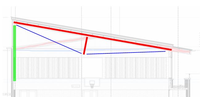
Hi, I’m designing what in principle appears to be a very simple truss… However the span is in the order of 18 m, and if you look at the attached diagram, the red members are glulam (doubles with connector plates in between) and the horizontal blue Line is a macalloy bar.

Are there any pitfalls I need to look out for here? The roof is heavy enough to resist wind uplift and is in a non seismic zone.

Axial forces are approx 400kN - anyone have any neat connection ideas?!!
 
 https://files.engineering.com/getfile.aspx?folder=ae003414-4d9c-409c-95fb-619fee88585a&file=010EAECE-7717-492F-82AD-5E3EF0A4FA32.jpeg
Replies continue below

Recommended for you

MIRE said:
Are there any pitfalls I need to look out for here?

It needs to be sexier. Seriously. There's an elegance sweet spot with these things and I just don't feel that you're there.

I also don't love how the top of the left wall is braced only by that shallow strut that will make for a fairly long compression member.

c01_jjsugr.jpg
 
I’m with you on that. Your markup is what I wanted. The provided scheme is the architects preference.
 
Haven't we previously discussed stability concerns with trusses like this?

(nevermind, I was looking at KootK's drawing and not the OP's)
 
I think the biggest pitfall is going to be resisting that 400kN load (especially at connections), though it wasn't clear where this was or if tension/compression, etc. That's a pretty big load for timber to go through typical connections you might associate with a truss.

I'm guessing at some point it's going to need to be taken in bearing by either member on member or by some sort of connectors (bolts, etc). It equates to a whole lot of bolts, which may end up driving the member size up. You need a pretty large area in bearing if reliant on members bearing perpendicular to the grain for example to resist a 400 kN load.

Some parts of the load path might be far more efficient in steel. Clad in timber to disguise it as timber if its required architecturally.
 
Not sure what a macalloy bar is, but I would design the end connections to have the tensile forces taken in end bearing on the wood beams. You could pass the bar between the beams and pass the end through a plate and then tighten with a nut on a threaded rod end. Bolted connections will slip and put more of the load into the beam in bending. Having the threaded rod connection allows you to preload the top chord and fine tune by measuring the upward camber. Be careful of suction loads on roof, make sure you have sufficient capacity upwards also.
 
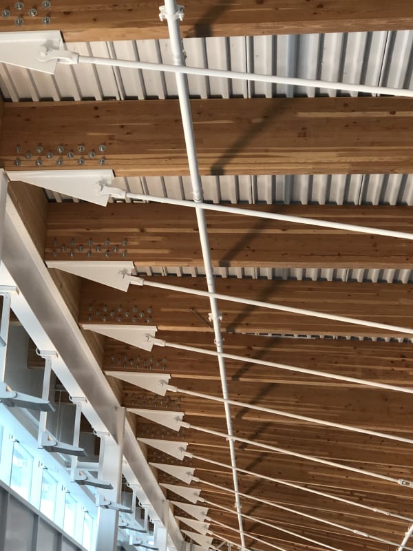
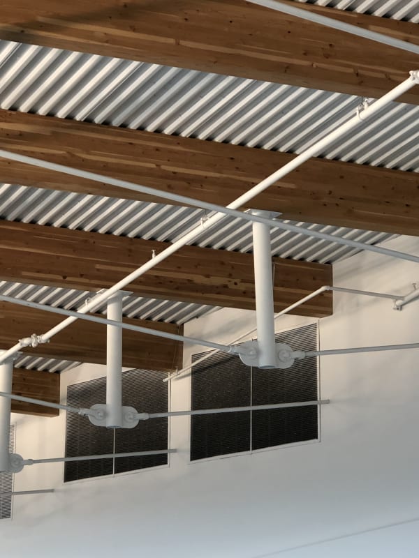
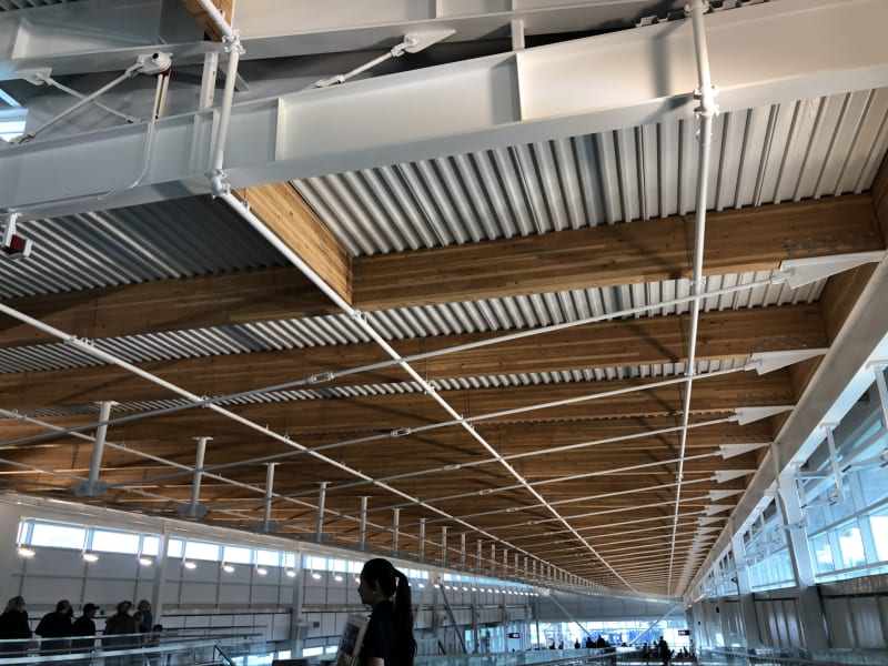
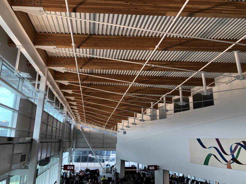
i thought these were pretty cool
at Seattle airport. (XR250 i missed the discussion on stability if it was related to this style and would appreciate the thread if available, thanks)
i don't think the planes landed on them though.
IMG_0229_tdg1zm.jpg
IMG_0230_gqxv6n.jpg
IMG_0228_oj4ifo.jpg
IMG_0227_bwufzf.jpg
 

Those do look cool. I'd also like to see the thread on the stability of these things. The king post is fixed - free for out of plane buckling, and any eccentricity from the cable increases the moment, so you need a connection with decent moment connection.

Asides from the post buckling w.r.t. the beam, is also seems you have to worry about LTB, even if the top flange is continuously braced.
 
I’ve also seen the threads, AISC papers, etc on the tension chord bracing issue. Someone needs to do a load test on one of these already so we can put it to rest. There’s no way that the verticals give enough out of plane stiffness to stabilize the truss, has to be through catenary action in the rod. Either way, they keep working and are nice to look at on the way to catching a flight.
 
cal91 said:
I'd also like to see the thread on the stability of these things.

txeng91 said:
Someone needs to do a load test on one of these already so we can put it to rest.

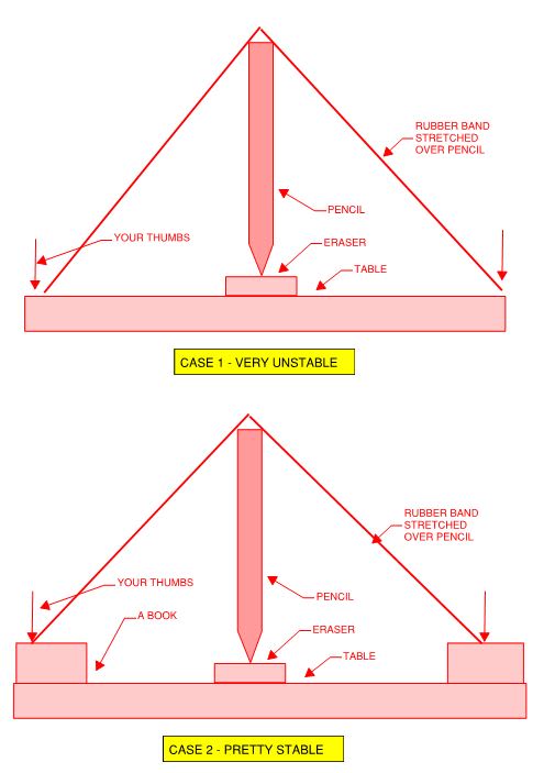
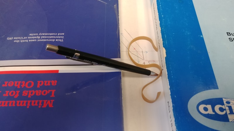
I believe that this can be explained by way of an old professor's trick used to demonstrate bridge stability. If anybody hasn't physically tried this, they really ought to as the effect is dramatic. Best done with a friend to hold the eraser if you've got one of those.

Step 1: do the experiment or recall it vividly if you've done it before.

Step 2: flip the experiment upside down in your head.

Step 3: consider how the upside down experiment compares to the king post truss. In particular, the significance of the tie rod connection being below the centroid of the glulam.

c01_eyvkea.jpg


HELP! I'd like your help with a thread that I was forced to move to the business issues section where it will surely be seen by next to nobody that matters to me:
 
Koot - that makes no sense in my head but I’ll have to try it out.

Cal - I misread your response. If you search “tension chord bracing” there’s a few. The one XR250 is referring to might actually be one of mine.


For the record I ended up running the bottom chord continuous to the column supports and designing it for out of plane forces per the AISC document. In this case I had the luxury of an all steel truss with a beefy bottom chord so it worked out fine.
 
OK, I would seriously like to know how many desktop experiments and free-body diagrams KootK's sketches above prompted..

0829191025_nogjsm.jpg


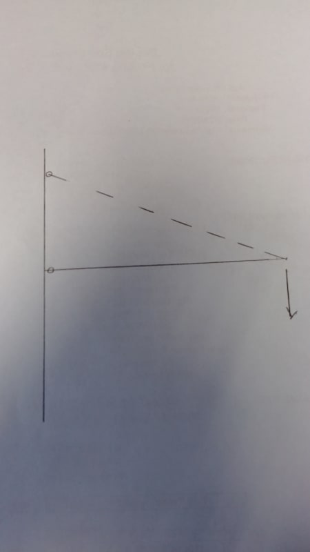
This condition reminds me of thinking through stability of a jib crane boom. Similar forces on the boom with the joad @ the location of the hanger rod as the king post above - and with a true hinge @ the connection!

0829191043_lv98hn.jpg
 
Status
Not open for further replies.

Part and Inventory Search

Sponsor